8.7 KiB
Compliling and Programming (STM32)
If you are Compling for the Arduino ATmega328p version of the Multiprotocol Module please go to the dedicated Compiling and Programming ATmega328 page.
IMPORTANT NOTE:
Multiprotocol source can be compiled using the Arduino IDE using STM32 Core (Maple) and Arduino ARM-Cortex-M3 libraries. On all modules with STM32F103 microcontroller, the program flash memory on the microcontroller is large enough to accommodate all the protocols. You do not have to make choices on which protocols to upload. Also, it is likely that you used the Banggood 4-in-1 RF module and you will therefore have access to all the RF modules.Now for programmng multimodule with STM32 chip you have 2 options presented below.
- Compiling and flashing in Arduino IDE.
- Flashing precompiled binaries from here
- If using one of these TX with multimodule like Turnigy 9X,9XR,9X+ the binary file for flashing is Multiprotocol_V1.X.X_STM32.bin.
- If using TARANIS TX the binary file is Multiprotocol_V1.X.X_STM32_INV.bin
Flashing precompiled binaries is done very simple with the cable setup presented below and an utility(GUI) ST Flash Loader Demonstrator.
Compiling source and flashing in Arduino.
Install the Arduino IDE and the Multiprotocol project
- Download the Arduino IDE. The currently supported Arduino version is 1.6.11 available for Windows and Mac OSX
- It is recommended to upgrade Java to the latest version
- Download the STM32 Core and copy the Arduino_STM32 folder to:
- OSX:
Arduino.app/Contents/Java/hardware(you can open Arduino.app by Ctl Clicking on Arduino.app and selecting "Show Package Contents") - Windows:
C:\Program Files (x86)\Arduino\hardware - Make sure the folder tree structure is like this .....\hardware\Arduino_STM32.....and NOT ...... \hardware\Arduino_STM32-master\Arduino_STM32-master......So move the folders /rename accordingly.
- Download the zip file with the Multiprotocol module source code from here
- Unzip and copy the source code folder
Multiprotocolto a folder of your choosing - Click on the
Multiprotocol.ino filein theMultiprotocolfolder and the Arduino environment should appear and the Multiprotocol project will be loaded.
Prepare the Arduino IDE:
- In order to compile successfully you need also to modify a maple library file. In
....\hardware\Arduino_STM32\STM32F1\cores\maple\libmaple\usart_f1.ccomment out the 2 functions as shown below. This is required to have low-level access to the USART interrupt.
/* void __irq_usart2(void){
usart_irq(&usart2_rb, USART2_BASE);
}
void __irq_usart3(void) {
usart_irq(&usart3_rb, USART3_BASE);
} */
- Run the IDE, and on the Tools menu, select Board and then Boards manager. Click on the Arduino DUE (32 Bits ARM-Cortex M3) from the list of available boards. You must do this step, it installs the arm-none-eabi-g++ toolchain!
- Close and reopen the Arduino IDE and load the Multiprotocol project.
- In arduino IDE under the Tools -> Board: select the Generic STM32F103C series board
- Click on the Verify button to test compile the before you make any changes. If there are any errors check the process above and be sure to have the right version of the Arduino IDE.The binary file generated location is presented at the bottom of Arduino IDE compiling window.Now continue with flashing procedure.
Flashing the multimodule
There are three options for flashing the firmware. But We will present here only 2 methods ,the third one is presented in advanced topics. The first (and strongly recommended) is flashing it while it is plugged into and powered by the transmitter.The second is preparing the board for flashing with a USB cable. The second method is definitely the easiest in the long-term, but it does require the USB bord and setting up the bootloader on the STM32 MCU.
Option 1: Flashing with Tx power(highly recommended)
- Put the module in the Tx
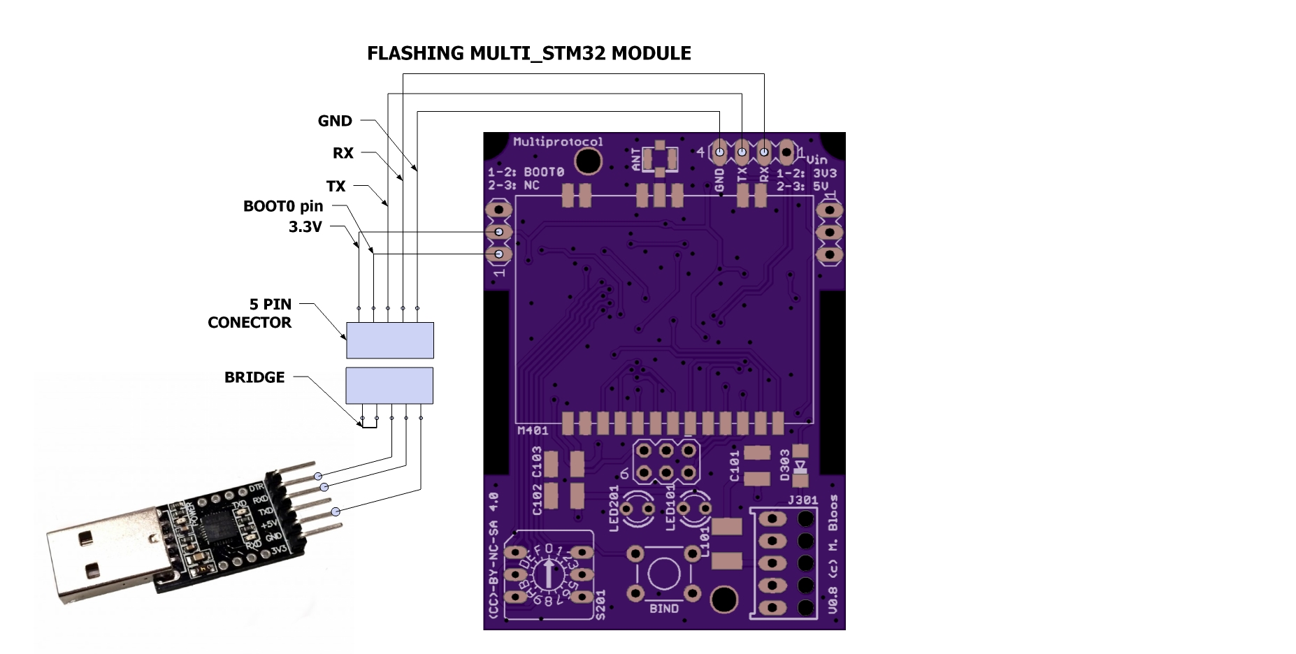
- Place a jumper over the BOOT0 pins.Skip this one if you made your own cable for flashing ,see below.
- Connect your 3.3V/5V FTDI cable (USB - TTL serial) to Multiprotocol serial port. Connect only RX, TX and GND. Do not connect the 5V or 3.3V between the FTDI cable and the module - the power will be supplied by the transmitter. Connect the pins as follows:
- Module RX pin to FTDI TX pin
- Module TX pin to FTDI Rx pin
- Module GND to FTDI GND
- In arduino IDE under the Tools -> Board: check that you have selected the Generic STM32F103C series board
- Under Tools -> Upload Method: select Serial
- Click "Upload" and the sketch will be uploaded normally. This is valid for all arduino versions.
- Once the firmware has uploaded, remove the BOOT0 jumper.
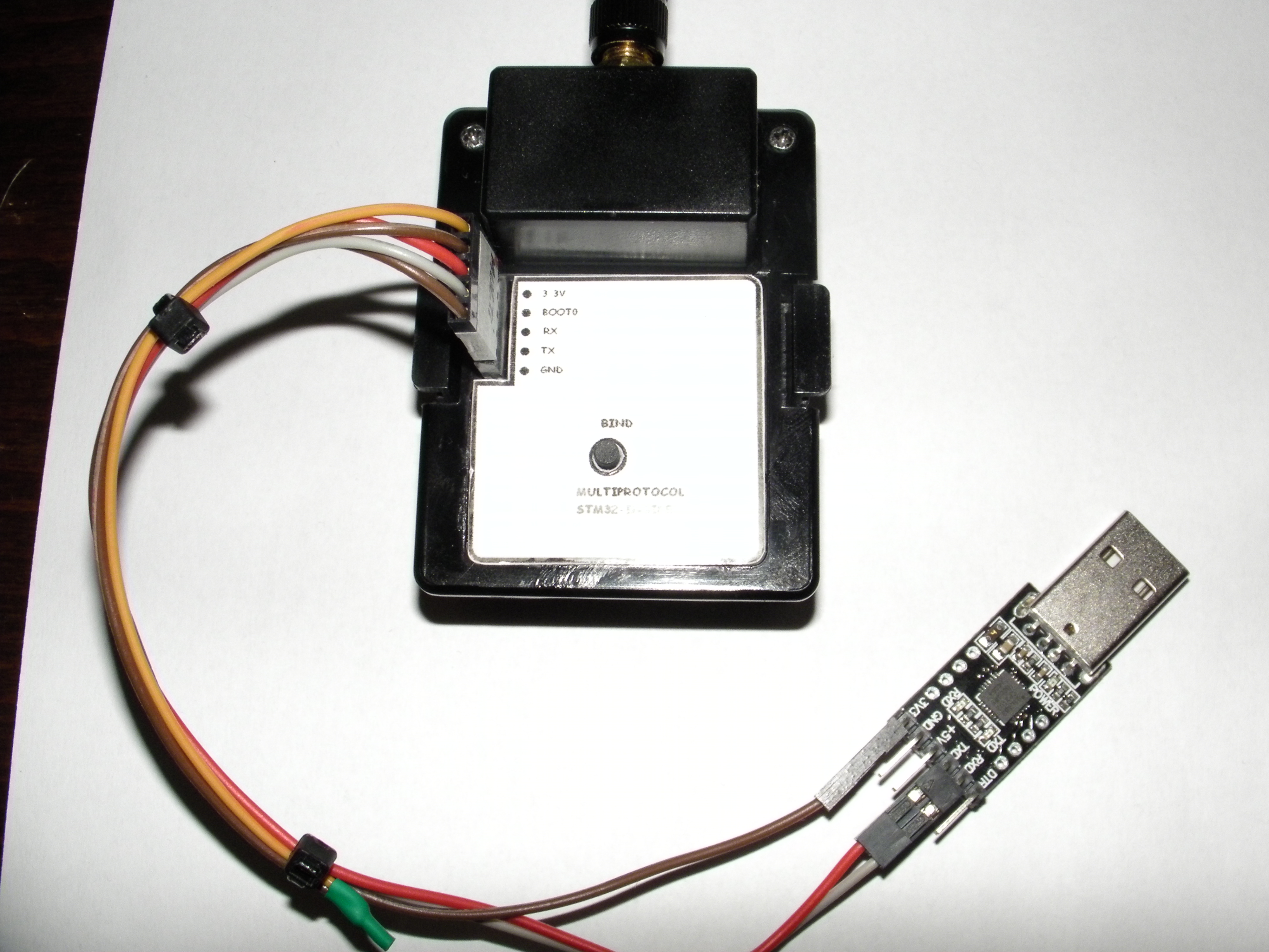
If you have the module inside a box and to be inserted in TX bay, you may build a flashing cable like in the picture below. You can attach and solder a 5 pin header female and top outside the box.ALways insert first the USB serial device in USB port , and TX start after.

See below my module for reference

Option 2: Flashing with USB cable.
This method use USB connector on the STM32 V1.0 board or on the maple clone board.
- Install first maple USB driver by running the batch file found in Arduino STM32 package folder "..\hardware\Arduino_STM32\drivers\win\install_drivers.bat"
- Download the free STM32 flash loader demonstrator from ST.com and using a USB-TTL device (like FTDI cable) flash the STM32duino bootloader available from Roger Clark's great STM32 site here .Use bootloader generic_boot20_pa1.bin
- Open Arduino IDE,browse to multiprotocol folder,load the sketch multiprotocol.ino.
- In Arduino IDE under "Upload method" select STM32duino-bootloader.Click upload ,wait until upload is complete.
Notes:
- When you use multiSTM32_USB for the first time,the USB drivers are not recognized and port is not open/recognized(arduino IDE port selection is grey/unavailable). After this first time use, any subsequent update of the program, you'll have to select the correct serial port and upload sketches normally in Arduino using USB port.
- If the initial upload fails, make sure you are running the latest Java version
Flashing precompiled binaries:
If you want to flash a pre-compiled binary file (like the Release .bin files) you need specialized software and the same FTDI cable setup already posted here.
- Set BOOT0 jumper(skip this step if you aready made your own cable ,see above)
- Connect your 3.3V FTDI cable (USB - TTL serial) to Multiprotocol serial port (RX,TX,GND pins when flashing with TX power).
- Insert first FTDI serial to USB port.Start TX (only if using flashing with TX power method)
- The other steps regarding power supply the same as previous recommandation regarding jumpers
For uploading binaries(.bin files) there is a specialized software you need to install on your computer.
Windows:
Download the ST Flash Loader Demonstrator from here: http://www.st.com/content/st_com/en/products/development-tools/software-development-tools/stm32-software-development-tools/stm32-programmers/flasher-stm32.html
Run the ST Flash Loader program. There are many tutorials on the web on how to use this program.For example
OSX:
To be checked.
###Report issues for the STM32 board You can report your problem using the GitHub issue system or go to the Main thread on RCGROUPS to ask your question. Please provide the following information:
- Multiprotocol code version
- STM32 version
- TX type
- Using PPM or Serial, if using er9x or ersky9x the version in use
- Different led status (multimodule and model)
- Explanation of the behavior and reproduction steps