mirror of
https://github.com/pascallanger/DIY-Multiprotocol-TX-Module.git
synced 2025-07-02 19:29:21 +00:00
453 lines
18 KiB
Markdown
453 lines
18 KiB
Markdown
# DIY-Multiprotocol-TX-Module
|
|
Multiprotocol is a 2.4GHz transmitter which enables any TX to control lot of different models available on the market.
|
|
|
|
The source code is partly based on the Deviation TX project, thanks to all the developpers for their great job on protocols.
|
|
|
|
[Forum link on RCGROUPS](http://www.rcgroups.com/forums/showthread.php?t=2165676) for additional information or requesting a new protocol integration.
|
|
|
|
|
|
|
|
**To download the latest compiled version (hex file), click on [Release](https://github.com/pascallanger/DIY-Multiprotocol-TX-Module/releases) on the top menu.**
|
|
|
|
##Contents
|
|
|
|
[Compatible TX](https://github.com/pascallanger/DIY-Multiprotocol-TX-Module#compatible-tx)
|
|
|
|
[Protocols](https://github.com/pascallanger/DIY-Multiprotocol-TX-Module#protocols)
|
|
|
|
[Hardware](https://github.com/pascallanger/DIY-Multiprotocol-TX-Module#hardware)
|
|
|
|
[Compilation and programmation](https://github.com/pascallanger/DIY-Multiprotocol-TX-Module#compilation)
|
|
|
|
[Troubleshooting](https://github.com/pascallanger/DIY-Multiprotocol-TX-Module#troubleshooting)
|
|
|
|
##Compatible TX
|
|
|
|
###Using standard PPM output (trainer port)
|
|
The multiprotocol TX module can be used on any TX with a trainer port.
|
|
|
|
Channels order is AETR by default but can be changed in the source code.
|
|
|
|
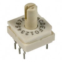
The protocol selection is done via a dip switch or a rotary dip switch for access to up to 15 different protocols.
|
|
|
|
|
|
|
|
###Using a serial output
|
|
The multiprotocol TX module takes full advantage of being used on a Turnigy 9X, 9XR, 9XR Pro, Taranis, 9Xtreme, AR9X, ... running [er9x or ersky9X](https://github.com/MikeBland/mbtx/tree/next). (A version for OpenTX is being looked at)
|
|
|
|
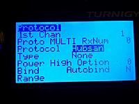
This enables full integration using the radio GUI to setup models with all the available protocols options.
|
|
|
|
|
|
|
|
Options are:
|
|
- Protocol and type: many main protocols have variants
|
|
- RX Num: number your different RXs and make sure only one model will react to the commands
|
|
- Power: High or low, enables to lower the power setting of your TX (indoor for example).
|
|
- Option: -127..+127 allowing to set specific protocol options. Like for Hubsan to set the video frequency.
|
|
- Bind: bind a RX/model
|
|
- Autobind: Yes or No. At the model selection (or power applied to the TX) a bind sequence will be initiated
|
|
- Range: test range by setting the transmission power to the lowest value
|
|
|
|
Notes:
|
|
- Using this solution does not need any modification of the TX since it uses the TX module slot PPM pin for serial transfer.
|
|
- There are 2 versions of serial protocol either 8 or 16 channels. 16 channels is the latest version. Make sure to use the right version based on your version of er9x/ersky9x.
|
|
- Channels order is AETR by default but can be changed in the source code.
|
|
|
|
###Telemetry
|
|
Telemetry is available for er9x and ersky9x TXs.
|
|
There are only 2 protocols so far supporting telemetry: Hubsan and Frsky.
|
|
|
|
To enable telemetry on Turnigy 9X or 9XR you need to modify your TX following one of the Frsky mod like this [one](http://blog.oscarliang.net/turnigy-9x-advance-mod/).
|
|
|
|
Enabling telemetry on 9XR PRO and may be other TXs does not require any hardware modifications. The additional required serial pin is already available on the TX back module pins.
|
|
|
|
Once the TX is telemetry enabled, it just needs to be configured on the model as usual.
|
|
|
|
##Protocols
|
|
|
|
###TX ID
|
|
The multiprotocol TX module is using a 32bits ID generated randomly at first power up. This global ID is used by all protocols.
|
|
There are little chances to get a duplicated ID.
|
|
|
|
It's possible to generate a new ID using bind button on the Hubsan protocol during power up.
|
|
|
|
###Bind
|
|
To bind a model in PPM Mode press the physical bind button, apply power and then release.
|
|
|
|
In Serial Mode you have 2 options:
|
|
- use the GUI, access the model protocol page and long press on Bind. This operation can be done at anytime.
|
|
- press the physical bind button, apply power and then release. It will request a bind of the first loaded model protocol.
|
|
|
|
Notes:
|
|
- the physical bind button is only effective at power up. Pressing the button later has no effects.
|
|
- a bind in progress is indicated by the LED fast blinking. Make sure to bind during this period.
|
|
|
|
###Protocol selection
|
|
|
|
####Using the dial for PPM input
|
|
PPM is only allowing access to a subset of existing protocols & sub_protocols.
|
|
The default association dial position / protocol is listed below.
|
|
|
|
Dial|Protocol|Sub_protocol|RF Module
|
|
----|--------|------------|---------
|
|
0|Select serial||
|
|
1|FLYSKY|Flysky|A7105
|
|
2|HUBSAN|-|A7105
|
|
3|FRSKY|-|CC2500
|
|
4|HISKY|Hisky|NRF24L01
|
|
5|V2X2|-|NRF24L01
|
|
6|DSM2|DSM2|CYRF6936
|
|
7|DEVO|-|CYRF6936
|
|
8|YD717|YD717|NRF24L01
|
|
9|KN|-|NRF24L01
|
|
10|SYMAX|SYMAX|NRF24L01
|
|
11|SLT|-|NRF24L01
|
|
12|CX10|CX10_BLUE|NRF24L01
|
|
13|CG023|CG023|NRF24L01
|
|
14|BAYANG|-|NRF24L01
|
|
15|SYMAX|SYMAX5C|NRF24L01
|
|
|
|
Notes:
|
|
- The dial selection must be done before the power is applied.
|
|
- The protocols and subprotocols accessible by the dial can be personalized by modifying the source code.
|
|
|
|
####Using serial input with er9x/ersky9x
|
|
Serial is allowing access to all existing protocols & sub_protocols listed below.
|
|
|
|
Protocol|Sub_protocol|RF Module
|
|
--------|------------|---------
|
|
Flysky||A7105
|
|
|Flysky
|
|
|V9x9
|
|
|V6x6
|
|
|V912
|
|
Hubsan||A7105
|
|
Frsky||CC2500
|
|
Hisky||NRF24L01
|
|
|Hisky
|
|
|HK310
|
|
V2x2||NRF24L01
|
|
DSM2||CYRF6936
|
|
|DSM2
|
|
|DSMX
|
|
Devo||CYRF6936
|
|
YD717||NRF24L01
|
|
|YD717
|
|
|SKYWLKR
|
|
|SYMAX2
|
|
|XINXUN
|
|
|NIHUI
|
|
KN||NRF24L01
|
|
SymaX||NRF24L01
|
|
|SYMAX
|
|
|SYMAX5C
|
|
SLT||NRF24L01
|
|
CX10||NRF24L01
|
|
|CX10_GREEN
|
|
|CX10_BLUE
|
|
|DM007
|
|
CG023||NRF24L01
|
|
|CG023
|
|
|YD829
|
|
|H8_3D
|
|
Bayang||NRF24L01
|
|
FrskyX||CC2500
|
|
|
|
Note:
|
|
- The dial should be set to 0 for serial. Which means all protocol selection pins should be left unconnected.
|
|
|
|
###Protocol details
|
|
Extended limits supported: -125%..+125% can be used and will be transmitted. Otherwise the default is -100%..+100% only.
|
|
|
|
Autobind protocol: you do not need to press the bind button at power up to bind, this is done automatically.
|
|
|
|
####BAYANG
|
|
Models: EAchine H8(C) mini, BayangToys X6/X7/X9, JJRC JJ850, Floureon H101 ...
|
|
|
|
Autobind protocol
|
|
|
|
CH1|CH2|CH3|CH4|CH5|CH6|CH7|CH8|CH9|CH10|CH11|CH12|CH13|CH14|CH15|CH16
|
|
---|---|---|---|---|---|---|---|---|----|----|----|----|----|----|----
|
|
A|E|T|R|FLIP|RTH|PICTURE|VIDEO|HEADLESS|INVERTED
|
|
|
|
####CG023
|
|
Models: EAchine CG023/CG031/3D X4
|
|
|
|
Autobind protocol
|
|
|
|
CH1|CH2|CH3|CH4|CH5|CH6|CH7|CH8|CH9|CH10|CH11|CH12|CH13|CH14|CH15|CH16
|
|
---|---|---|---|---|---|---|---|---|----|----|----|----|----|----|----
|
|
A|E|T|R|FLIP|LIGHT|PICTURE|VIDEO|HEADLESS
|
|
|
|
#####Sub_protocol YD829
|
|
Models: Attop YD-822/YD-829/YD-829C ...
|
|
|
|
CH5|CH6|CH7|CH8|CH9
|
|
---|---|---|---|---
|
|
FLIP||PICTURE|VIDEO|HEADLESS
|
|
|
|
#####Sub_protocol H8_3D
|
|
Models: EAchine H8 mini 3D, JJRC H20/H22
|
|
|
|
CH5|CH6|CH7|CH8|CH9
|
|
---|---|---|---|---
|
|
FLIP|OPT1|OPT2|OPT3|OPT4
|
|
|
|
JJRC H20: OPT1=Headless, OPT2=RTH
|
|
|
|
JJRC H22: OPT2=RTH, OPT3=LIGTH, OPT4=360° flip mode
|
|
|
|
H8 3D: OPT1=RTH + headless, OPT2=360° flip mode
|
|
|
|
Both sticks bottom left: calibrate accelerometers
|
|
|
|
####CX10
|
|
Extended limits supported
|
|
|
|
Autobind protocol
|
|
|
|
CH1|CH2|CH3|CH4|CH5|CH6|CH7|CH8|CH9|CH10|CH11|CH12|CH13|CH14|CH15|CH16
|
|
---|---|---|---|---|---|---|---|---|----|----|----|----|----|----|----
|
|
A|E|T|R|FLIP|MODE
|
|
|
|
MODE: +100%=mode3 or headless for CX-10A, -100%=mode1, 0%=mode2
|
|
|
|
#####Sub_protocol CX10_GREEN
|
|
Cheerson CX-10 green pcb
|
|
|
|
Same channels assignement as above.
|
|
|
|
#####Sub_protocol CX10_BLUE
|
|
Cheerson CX-10 blue pcb & some newer red pcb, CX-10A, CX-10C, CX11, CX12, Floureon FX10, JJRC DHD D1
|
|
|
|
Same channels assignement as above.
|
|
|
|
#####Sub_protocol CX10_DM007
|
|
|
|
CH5|CH6|CH7|CH8|CH9
|
|
---|---|---|---|---
|
|
FLIP|MODE|PICTURE|VIDEO|HEADLESS
|
|
|
|
####DEVO
|
|
Extended limits supported
|
|
|
|
CH1|CH2|CH3|CH4|CH5|CH6|CH7|CH8|CH9|CH10|CH11|CH12|CH13|CH14|CH15|CH16
|
|
---|---|---|---|---|---|---|---|---|----|----|----|----|----|----|----
|
|
CH1|CH2|CH3|CH4|CH5|CH6|CH7|CH8
|
|
|
|
####DSM2
|
|
Extended limits supported
|
|
|
|
CH1|CH2|CH3|CH4|CH5|CH6|CH7|CH8|CH9|CH10|CH11|CH12|CH13|CH14|CH15|CH16
|
|
---|---|---|---|---|---|---|---|---|----|----|----|----|----|----|----
|
|
A|E|T|R|CH5|CH6|CH7|CH8
|
|
|
|
####FLYSKY
|
|
Extended limits supported
|
|
|
|
CH1|CH2|CH3|CH4|CH5|CH6|CH7|CH8|CH9|CH10|CH11|CH12|CH13|CH14|CH15|CH16
|
|
---|---|---|---|---|---|---|---|---|----|----|----|----|----|----|----
|
|
A|E|T|R|CH5|CH6|CH7|CH8
|
|
|
|
#####Sub_protocol V9X9
|
|
CH5|CH6|CH7|CH8
|
|
---|---|---|---
|
|
UNK|LIGHT|PICTURE|VIDEO
|
|
|
|
#####Sub_protocol V6X6
|
|
CH5|CH6|CH7|CH8|CH9|CH10|CH11|CH12
|
|
---|---|---|---|---|---|---|---
|
|
FLIP|LIGHT|PICTURE|VIDEO|HEADLESS|RTH|XCAL|YCAL
|
|
|
|
#####Sub_protocol V912
|
|
CH5|CH6
|
|
---|---
|
|
BTMBTN|TOPBTN
|
|
|
|
####FRSKY
|
|
Extended limits supported
|
|
|
|
Telemetry enabled for A0, A1, RSSI
|
|
|
|
Option=fine frequency tuning, usually 0 or -41 based on the manufacturer boards
|
|
|
|
CH1|CH2|CH3|CH4|CH5|CH6|CH7|CH8|CH9|CH10|CH11|CH12|CH13|CH14|CH15|CH16
|
|
---|---|---|---|---|---|---|---|---|----|----|----|----|----|----|----
|
|
CH1|CH2|CH3|CH4|CH5|CH6|CH7|CH8
|
|
|
|
####HISKY
|
|
CH1|CH2|CH3|CH4|CH5|CH6|CH7|CH8|CH9|CH10|CH11|CH12|CH13|CH14|CH15|CH16
|
|
---|---|---|---|---|---|---|---|---|----|----|----|----|----|----|----
|
|
A|E|T|R|GEAR|PITCH|GYRO|CH8
|
|
|
|
GYRO: -100%=6G, +100%=3G
|
|
|
|
####HK310
|
|
Models: RX HK-3000 and HK3100
|
|
|
|
CH1|CH2|CH3|CH4|CH5|CH6|CH7|CH8|CH9|CH10|CH11|CH12|CH13|CH14|CH15|CH16
|
|
---|---|---|---|---|---|---|---|---|----|----|----|----|----|----|----
|
|
|||T|R|AUX|T_FSAFE|R_FSAFE|AUX_FSAFE
|
|
|
|
####HUBSAN
|
|
Autobind protocol
|
|
|
|
Telemetry enabled for battery voltage only
|
|
|
|
Option=vTX frequency (H107D) 5645 - 5900 MHz
|
|
|
|
CH1|CH2|CH3|CH4|CH5|CH6|CH7|CH8|CH9|CH10|CH11|CH12|CH13|CH14|CH15|CH16
|
|
---|---|---|---|---|---|---|---|---|----|----|----|----|----|----|----
|
|
A|E|T|R|FLIP|LIGHT||VIDEO
|
|
|
|
####KN
|
|
CH1|CH2|CH3|CH4|CH5|CH6|CH7|CH8|CH9|CH10|CH11|CH12|CH13|CH14|CH15|CH16
|
|
---|---|---|---|---|---|---|---|---|----|----|----|----|----|----|----
|
|
A|E|T|R|DR|THOLD|IDLEUP|GYRO3
|
|
|
|
GYRO3: -100%=6G, +100%=3G
|
|
|
|
####SLT
|
|
Autobind protocol
|
|
|
|
CH1|CH2|CH3|CH4|CH5|CH6|CH7|CH8|CH9|CH10|CH11|CH12|CH13|CH14|CH15|CH16
|
|
---|---|---|---|---|---|---|---|---|----|----|----|----|----|----|----
|
|
A|E|T|R|GEAR|PITCH
|
|
|
|
####Symax
|
|
Autobind protocol
|
|
|
|
CH1|CH2|CH3|CH4|CH5|CH6|CH7|CH8|CH9|CH10|CH11|CH12|CH13|CH14|CH15|CH16
|
|
---|---|---|---|---|---|---|---|---|----|----|----|----|----|----|----
|
|
A|E|T|R|FLIP||PICTURE|VIDEO|HEADLESS
|
|
|
|
#####Sub_protocol SYMAX
|
|
Models: Syma X5C-1/X11/X11C/X12
|
|
|
|
#####Sub_protocol SYMAX5C
|
|
Model: Syma X5C
|
|
|
|
####V2X2
|
|
Models: WLToys V202/252/272, JXD 385/388, JJRC H6C, Yizhan Tarantula X6 ...
|
|
|
|
CH1|CH2|CH3|CH4|CH5|CH6|CH7|CH8|CH9|CH10|CH11|CH12|CH13|CH14|CH15|CH16
|
|
---|---|---|---|---|---|---|---|---|----|----|----|----|----|----|----
|
|
A|E|T|R|FLIP|LIGHT|PICTURE|VIDEO|HEADLESS|MAG_CAL_X|MAG_CAL_Y
|
|
|
|
####YD717
|
|
Autobind protocol
|
|
|
|
CH1|CH2|CH3|CH4|CH5|CH6|CH7|CH8|CH9|CH10|CH11|CH12|CH13|CH14|CH15|CH16
|
|
---|---|---|---|---|---|---|---|---|----|----|----|----|----|----|----
|
|
A|E|T|R|FLIP|LIGHT|PICTURE|VIDEO|HEADLESS
|
|
|
|
#####Sub_protocol YD717
|
|
#####Sub_protocol SKYWLKR
|
|
#####Sub_protocol SYMAX2
|
|
#####Sub_protocol XINXUN
|
|
#####Sub_protocol NIHUI
|
|
Same channels assignement as above.
|
|
|
|
##Hardware
|
|
|
|
###RF modules
|
|
Up to 4 RF modules can be installed:
|
|
- [A7105](http://www.banggood.com/XL7105-D03-A7105-Modification-Module-Support-Deviation-Galee-Flysky-p-922603.html) for Flysky, Hubsan
|
|
- [CC2500](http://www.banggood.com/CC2500-PA-LNA-Romote-Wireless-Module-CC2500-SI4432-NRF24L01-p-922595.html) for Frsky
|
|
- [CYRF6936](http://www.ehirobo.com/walkera-wk-devo-s-mod-devo-8-or-12-to-devo-8s-or-12s-upgrade-module.html) for DSM2, DSMX, DEVO, Walkera
|
|
- [NRF24L01](http://www.banggood.com/2_4G-NRF24L01-PA-LNA-Wireless-Module-1632mm-Without-Antenna-p-922601.html) for Hisky, V2x2, CX-10, SYMAX and plenty other protocols
|
|
|
|
RF modules can be installed for protocols need only. Example: if you only need the Hubsan protocol then install only a A7105 on your board.
|
|
|
|
You also need some [antennas](http://www.banggood.com/2_4GHz-3dBi-RP-SMA-Connector-Booster-Wireless-Antenna-Modem-Router-p-979407.html) and [cables](http://www.banggood.com/10cm-PCI-UFL-IPX-to-RPSMA-Female-Jack-Pigtail-Cable-p-924933.html).
|
|
|
|
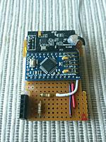
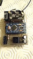
###Microcontroller
|
|
The main program is running on an ATMEGA328 running @16MHz and 3.3V.
|
|
An [Arduino pro mini](http://www.banggood.com/Wholesale-New-Ver-Pro-Mini-ATMEGA328-328p-5V-16MHz-Arduino-Compatible-Nano-Size-p-68534.html) can be used to build your own Multimodule.
|
|
|
|
Using stripboard:
|
|
|
|
|
|
|
|
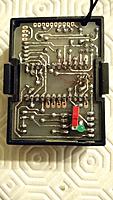
Using a [home made PCB](http://www.rcgroups.com/forums/showpost.php?p=32645328&postcount=1621):
|
|
|
|
|
|
|
|
|
|
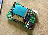
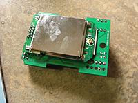
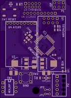
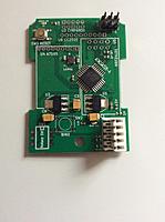
or build your own board using [SMD components](http://www.rcgroups.com/forums/showpost.php?p=31064232&postcount=1020) and an [associated PCB](https://oshpark.com/shared_projects/MaGYDg0y):
|
|
|
|
|
|
|
|
 
|
|
|
|
If you build this PCB v2.3c and want to enable serial mode for er9x/ersky9x, you should do [this mod](http://static.rcgroups.net/forums/attachments/4/0/8/5/8/3/a8180322-194-multi.jpg):
|
|

|
|
|
|
|
|
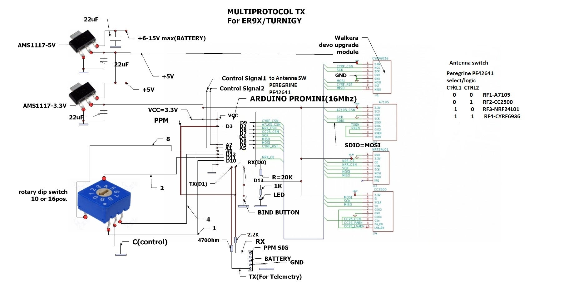
###Schematic
|
|
|
|
|
|
Notes:
|
|
- Attention: All modules are 3.3V only, never power them with 5V.
|
|
- For serial, the dial switch is not needed and the bind button optionnal
|
|
|
|
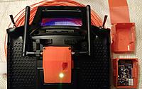
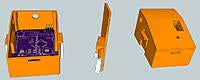
###Radio integration
|
|
You can 3D print your box (details [here](http://www.rcgroups.com/forums/showpost.php?p=33294140&postcount=2034)):
|
|
|
|
|
|
|
|
|
|
##Compilation and programmation
|
|
|
|
###Toolchain
|
|
Arduino 1.6.5
|
|
|
|
Compilation of the code posted here works. So if it doesn't for you this is a problem with your setup, please double check everything before asking.
|
|
|
|
Multiprotocol.ino header can be modified to compile with/without some protocols, change protocols/sub_protocols associated with dial for PPM input, different channel orders, different channels timing, 8 or 16 channels serial protocol, Telemetry or not, ...
|
|
|
|
###Upload the code using ISP (In System Programming)
|
|
It is recommended to use an external programmer like [USBASP](http://www.banggood.com/USBASP-USBISP-3_3-5V-AVR-Downloader-Programmer-With-ATMEGA8-ATMEGA128-p-934425.html) to upload the code in the Atmega328. The programmer should be set to 3.3V or nothing to not supply any over voltage to the multimodule and avoid any damages.
|
|
|
|
The dial must be set to 0 before flashing!
|
|
|
|
From the Arduino environment, you can use this shortcut to compile and upload to the module: Skecth->Upload Using Programmer (Ctrl+Maj+U)
|
|
|
|
To flash the latest provided hex file under [Release](https://github.com/pascallanger/DIY-Multiprotocol-TX-Module/releases), you can use a tool like [AVR Burn-O-Mat](http://avr8-burn-o-mat.aaabbb.de/), set the microcontroller to m328p and flash it.
|
|
|
|
###Set fuses
|
|
Use a tool like [AVR Burn-O-Mat](http://avr8-burn-o-mat.aaabbb.de/) to set the fuses of the Atmega328 to:
|
|
- Low Fuse 0xFF
|
|
- High Fuse 0xD2
|
|
- Extended Fuse 0x05
|
|
|
|
This will make sure your ATMEGA328 is well configured and the global TX ID is not erased at each updates.
|
|
|
|
##Troubleshooting
|
|
|
|
###LED status
|
|
- off: program not running or a protocol selected with the associated module not installed.
|
|
- slow blink: serial has been selected but no valid signal has been seen on the RX pin.
|
|
- fast blink: bind in progress.
|
|
- on: normal operation.
|
|
|
|
###Bind
|
|
Make sure to follow this procedure: press the bind button, apply power and then release it after 1sec. The LED should be blinking fast indicating a bind status and then fixed on when the bind period is over. It's normal that the LED turns off when you press the bind button, this behavior is not controlled by the Atmega328.
|
|
For serial, the preffered method is to bind via the GUI protocol page.
|
|
|
|
It migth happen that your module is always binding at power up. If this is the case, there is a big chance that you are using an Arduino Pro Mini with an external status LED. To work around this issue connect a 10K resistor between D13 and 3.3V.
|
|
|
|
###Protocol selection
|
|
For serial, leave all 4 selection pins unconnected.
|
|
For PPM, connect 1 to 4 of the selection protocol pins to GND.
|
|
The protocol/mode selection must be done before the power is applied.
|
|
|
|
###Report issues
|
|
You can report your problem using the [GitHub issue](https://github.com/pascallanger/DIY-Multiprotocol-TX-Module/issues) system or go to the [Main thread on RCGROUPS](http://www.rcgroups.com/forums/showthread.php?t=2165676) to ask your question.
|
|
Please provide the following information:
|
|
- Multiprotocol code version
|
|
- TX type
|
|
- Using PPM or Serial, if using er9x or ersky9x the version in use
|
|
- Different led status (multimodule and model)
|
|
- Explanation of the behavior and reproduction steps
|