10 KiB
Compiling and Programming (ATmega 328P)
If you are Compling for the STM32 version of the Multiprotocol Module please go to the dedicated Compiling and Programming STM32 page.
This page describes the basic Compiling and Programming process. There are some other more advanced processes that have some superior features described under the Advanced Topics page. Some options are:
- How to flash more protocols
- Using an FTDI cable to upload firmware over the module - Tx pins
If you wish to upload one of prepared binary files please see the page Manually programming and setting fuses.
Multiprotocol source can be compiled using the Arduino IDE.
##Install the Arduino IDE and the Multiprotocol project
- Download the Arduino IDE. The currently supported Arduino version is 1.6.12. available for Windows and Mac OSX
- Download the zip file with the Multiprotocol module source code from here
- Unzip and copy the source code folder Multiprotocol to a folder of your choosing
- Click on the Multiprotocol.ino file in the Multiprotocol folder and the Arduino environment should appear and the Multiprotocol project will be loaded.
Upload the firmware
If you are using the Banggood readymade 4-in-1 module or one of the DIY Mulitprotocol modules (like the 2.3d board) then follow these instructions.
If you have built a module with an Arduino Pro-Mini, you have 2 options to upload the firmware. Using an USBASP as explained below or using a USB to serial converter as explained here Programming Arduino Pro-Mini Boards
###Material you need to upload the firmware
- USBASP programmer supporting 3.3V:
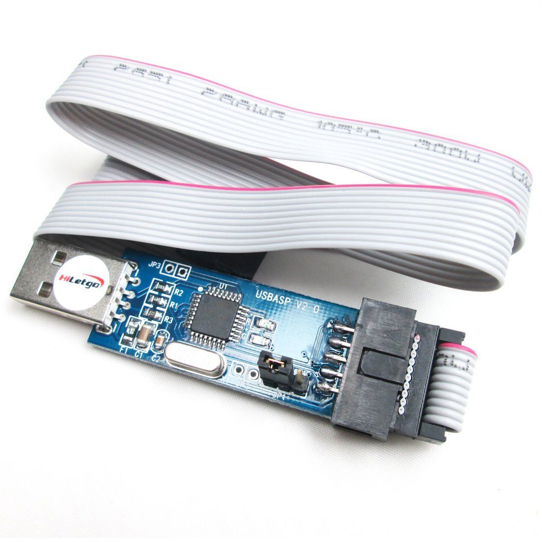 (example ebay link)
 - 10pin to 6pin adapter:
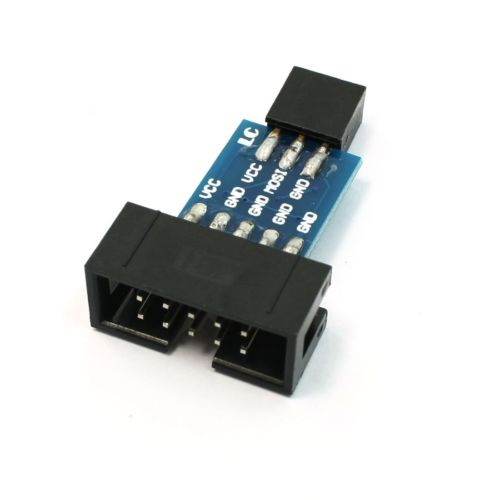 (example ebay link)
 - 6 pin header like this one:
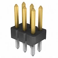 (example Digi-Key link)


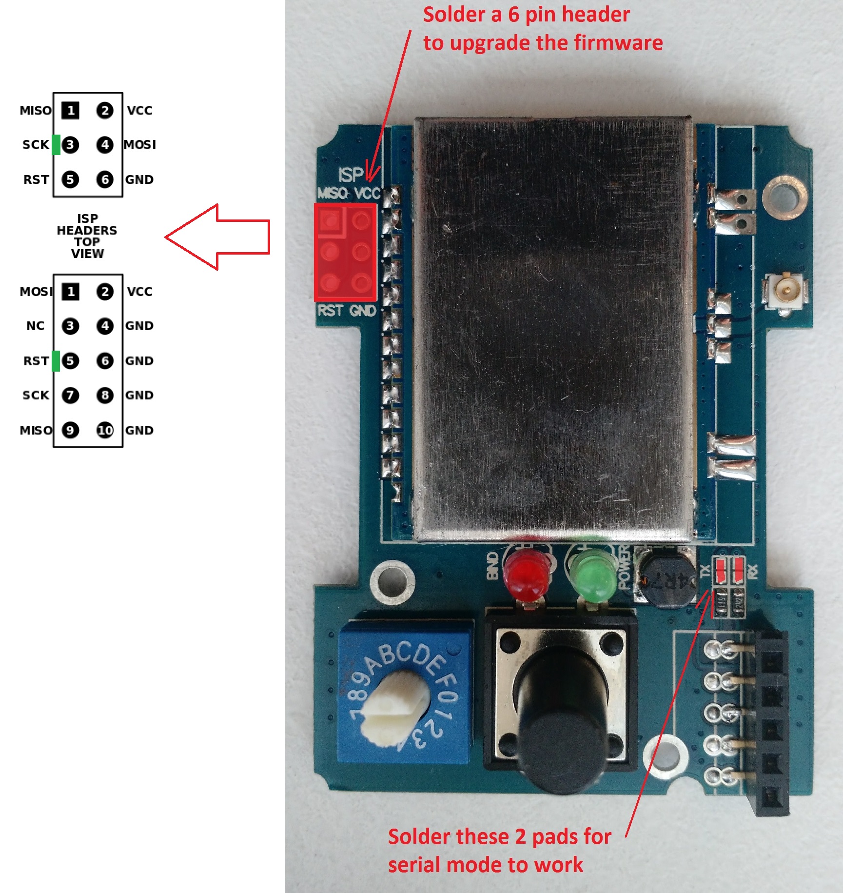
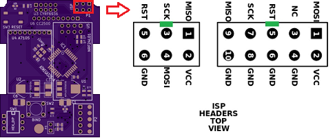
The 6 Pin header needs to be solder on the board like indicated by the red rectangle:
- Banggood readymade 4-in-1 module:
- DIY Mulitprotocol modules (like the 2.3d board):


If you are looking for a good working USBASP Windows driver, use this one.
###Configure Arduino IDE for Multiprotocol
- Under Tools -> Board select the Arduino Pro or Pro Mini
- Under Tools -> Processor select the ATmega328 (5V, 16MHz)
- Under Tools -> Programmer select your programmer type (probably USBASP)
###Customize the firmware to match your hardware and your needs
All customization is done by editing the _Config.h file in the Multiprotocol Arduino project.
In the Arduino IDE, click on the down arrow on the far right of the tab bar to show a list of project files (see the red circle on the screenshot below). Scroll down and select the _Config.h file.

The file has different sections which are explained in details. The best is to go through them one by one carefully and apply the configuration which matches your needs.
Most of the default settings should get you started quickly. But on modules with ATMega microcontrollers, the memory required for all the protocols exceeds the available 32k of flash memory. You therefore need to select which protocols you wish to use in order to fit them into the available memory.
To fill in the "PROTOCOLS TO INCLUDE" section, it would be good to review all the available protocols on the Protocol Details page and identify which one you would like to add on your module.
To check that the program will compile correctly and fit in the Atmega press the Check mark as shown below.

If you see something like the following, your firmware is still too big and you need to deselect additional protocols:
Sketch uses 34,096 bytes (104%) of program storage space. Maximum is 32,768 bytes. Global variables use 1,236 bytes (60%) of dynamic memory, leaving 812 bytes for local variables. Maximum is 2,048 bytes. Sketch too big.
If there is another error carefully read it, go to the line number indicated and correct your typo.
###Connect the programmer
-
Before you connect the programmer make sure that you have selected the 3.3V mode and not 5V. The RF Modules are not 5V tolerant and you will break them with 5V. On most programmers this is done by moving a jumper.

-
Please re-read item 1. above before going on.
-
Turn the rotary switch on the DIY Multiprotocol module to the 0 position. If you do not have a switch for Serial mode only then it is the same as being in the 0 position. The upload will not work if the switch is in any other position.
-
Connect the 6-pin programming connector to the 6-pin ASP IVR connector on the DIY Multiprotocol board. Be sure to match the ground pin of the programmer connector to the ground pin on the board (see the images below for the pin layout and the location of the ground pin on the board)
-
You are now ready to plug in the USB programmer to the computer
-
The first step is to flash the fuses of the microprocessor. These correct fuses will do a few things:

- Prevent the EEPROM from being erased each time the firmware is flashed. This will preserve your Tx ID and save you from having to rebind all your models after an update of the firmware
- Configure the clock source of the board - this is very important if you built the board from components. The ATMega328P microprocessor is configured at the factory to use an internal 8Mhz clock. The DIY Multiprotocol boards have a much more accurate 16MHz external crystal and the fuses will tell the MCU to use this clock source. (If you were able to flash the board but after setting the fuses the board no longer responds, it is very likely that you have a problem with your external clock.)
- Set the program counter to point at the right place when the module is powered up. The fuses configure the MCU to use a bootloader or not. If you compiled the firmware without a bootloader then the fuses must be set accordingly.
- In the Arduino IDE ensure that the 4-in-1 Multi is selected under Tools -> Board: click on Tools -> Burn Bootloader. Do not worry if it returns the error that no bootloader was found (in the case of the 4-in-1 board), it has burned the fuses. If you IDE was set to provide verbose compilation and uploading output, you should be able to see the final value of the fuses in the Arduino IDE.
- You are now ready to flash the firmware. In the Arduino IDE click Sketch -> Upload Using Programmer.
- If you get an error that indicates a valid microprocessor was not found there is something wrong with:
- your connections,
- your programmer, or
- your board
- Google around with the specific error message to get suggestions of how to fix it. The most common cause is problems with the connection setup and in some cases problems with the cheap programmers from Chinese sources.
If the output indicates that the fuses have been successfully written and the firmware has been uploaded - give yourself a pat on the back. Well done, you have successfully programmed your DIY Multiprotocol module and you are ready to go on to the final step Setting up your Transmitter before you can begin to fly!!!!
##Programming Arduino Pro-Mini Boards
Use this method only for Arduino Pro Mini boards with bootloader.
- Use an external FTDI adapter like one of these options:


- The programmer should be set to 3.3V or nothing to not supply any over voltage to the multimodule and avoid any damages.
- Under the Tools -> Board: select the Arduino Pro-Mini
- Under Tools -> Processor select the Atmega328p (5V, 16Mhz)
- Under Tools -> Port select your the serial port your programmer is connected to (it should appear on the the list)
- Scroll back to the section Customize the firmware to your hardware and your needs above and follow the instructions remembering that you can simply use the Upload button in the Arduino IDE to upload firmware using the Arduino bootloader:
- From the Arduino environment, you can use Upload button which will compile and upload to the module: Sketch->Upload (Ctrl+U)
- Note that the available flash memory for the firmware reduces by about 2K when you use the bootloader
To change the fuses you will need to use an external programmer (like USBasp mentioned above) and a flash tool that fits over the MCU and connects to the required pins, like this one:

It connects to the USBASP programmer and connects directly to the pins on the microcontroller and it will allow you to set fuses and to program the Pro-Mini like the 4-in-1 boards above, without using the bootloader.
Follow the instructions in Advanced Topics - Manually Setting Fuses to set the fuses.
If building the board from scratch was your chosen strategy we suspect that you would already know how to do this. If not, Google is your friend, try something like “how to flash fuses on Arduino pro-mini”.