# Compiling and Flashing (STM32)
Multiprotocol modules can be flashed with a precompiled firmware file (Option 1 and 2) or you can compile and upload your customized firmware using the Arduino IDE (Option 3).
**These instructions are for the STM32 version of the Multiprotocol module.** If you are Compling for the Arduino ATmega328p version of the Multiprotocol Module please go to the dedicated [ATmega328](Compiling.md) page.
## Index
1. [Tools Required](#tools-required)
1. [Option 1 - Update firmware using precompiled binaries](#option-1---update-firmware-using-precompiled-binaries)
1. [Option 2 - Flash from TX](#option-2---flash-from-tx)
1. [Option 3 - Compiling and updating firmware](#option-3---compiling-and-updating-firmware)
1. [Preparation](#preparation)
1. [Install the Arduino IDE](#install-the-arduino-ide)
1. [Download the Multiprotocol source and open the project](#download-the-multiprotocol-source-and-open-the-project)
1. [Install the Multi 4-in-1 board](#install-the-multi-4-in-1-board)
1. [Configure the Arduino IDE](#configure-the-arduino-ide)
1. [Configure the firmware](#configure-the-firmware)
1. [Verify the firmware](#verify-the-firmware)
1. [Connect the module](#connect-the-module)
1. [USB Port](#usb-port)
1. [USB-to-Serial adapter](#usb-to-serial-adapter)
1. [Upload the firmware](#upload-the-firmware)
1. [Option 4 - Flash via USB, using dfu-util (on Linux)](#option-4---flash-via-usb-using-dfu-util-on-linux)
1. [Troubleshooting](#troubleshooting)
## Tools required
Tools are only required if a multi module does not have a USB port, a working bootloader or an integrated FTDI adapter:
* The latest iRangeX IRX4+ modules most likely already have the USB Bootloader flashed on it. You therefore don't need the FTDI adapter below and don't need to open your module to flash it.
* The latest Jumper modules have an integrated FTDI appearing as a CP2102 device on the computer. You therefore don't need the FTDI adapter below and don't need to open your module to flash it.
* The Vantac MPM Lite module already has the USB Bootloader flashed on it. You therefore don't need the FTDI adapter below and don't need to open your module to flash it. **Modules' bootloader however might not be booting everytime depending on the radio, if this is the case you need to upgrade it.**
You are still unsure if your module can be flashed without tools or opening it? Here is how to quickly check:
* Power off the TX
* Connect a USB cable to the module, if the module does not have a USB port then you must open the module to flash it using an external FTDI
* Connect the cable to the PC and power on the the TX
* If the PC does not complain about a none working device being plugged then you are good to upgrade via USB directly without the need of any tools or opening the module.
Your multi module is not USB upgradable ready, here is what you need:
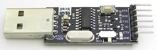
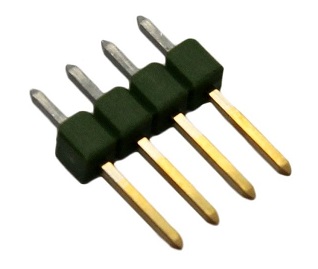
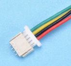
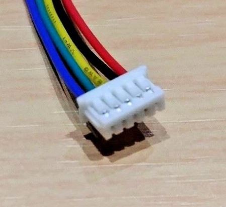
| **3.3V USB-TTL Adapter** | **4-pin 2.54mm Serial Programming Header** | **4-pin 1mm Serial Programming header + cable** | **5-pin 1.25mm cable** |
|:---:|:---:|:---:|:---:|
| All modules | DIY, Banggood 4-in-1, iRangeX IRX4/IRX4+/IRX4Lite, Jumper 4in1 1st gen | Vantac lite, URUAV lite | Jumper T16 internal module |
|  |
|  |
|  |
|  |
| [(example ebay link)](https://www.ebay.co.uk/itm/FTDI-USB-to-TTL-Serial-Converter-Adapter-FT232RL-Module-5V-and-3-3V-Arduino-ARM/231918152528) | [(example ebay link)](https://www.ebay.co.uk/itm/4x-826629-4-Pin-header-pin-strips-AMPMODU-MOD-II-male-PIN4-straight/192334571714) | [(example ebay link)](https://www.ebay.com/itm/5-PCS-Mini-Micro-ZH-1mm-2-6-Pin-JST-Connector-with-Wire-HI/183963001322) | [(example ebay link)](https://www.ebay.co.uk/itm/5-PAIRS-5-PIN-Micro-JST-GH-1-25-Connector-Plug-Socket-1-25mm-150mm-Cable/273110735668)
The USB-TTL adapter can be either FTDI or CH340G, as long as it works. It should have a switch or jumper to select 3.3V or 5V, which **must** be set to **3.3V**.
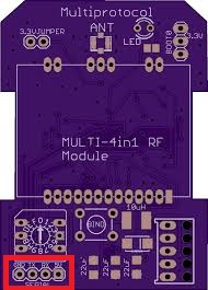
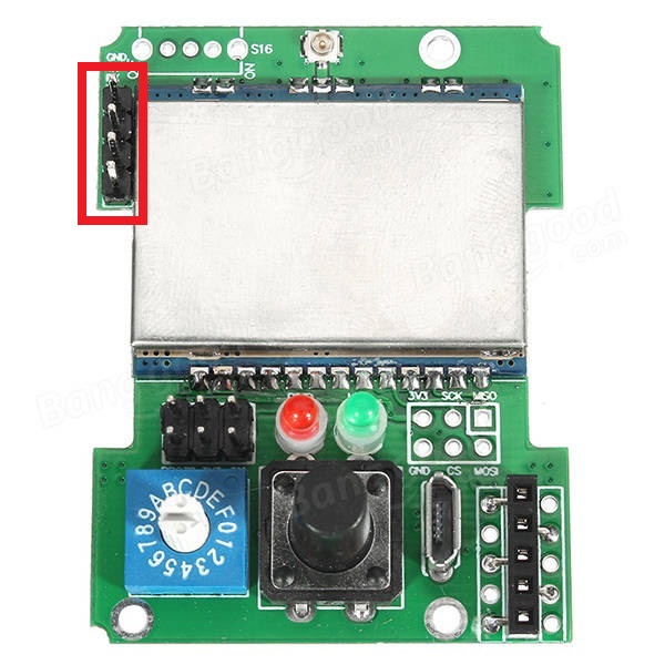
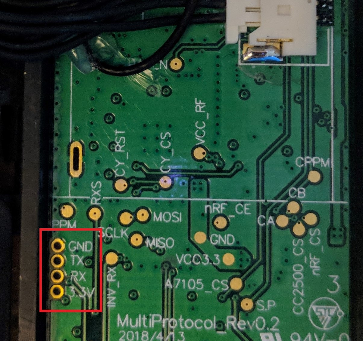
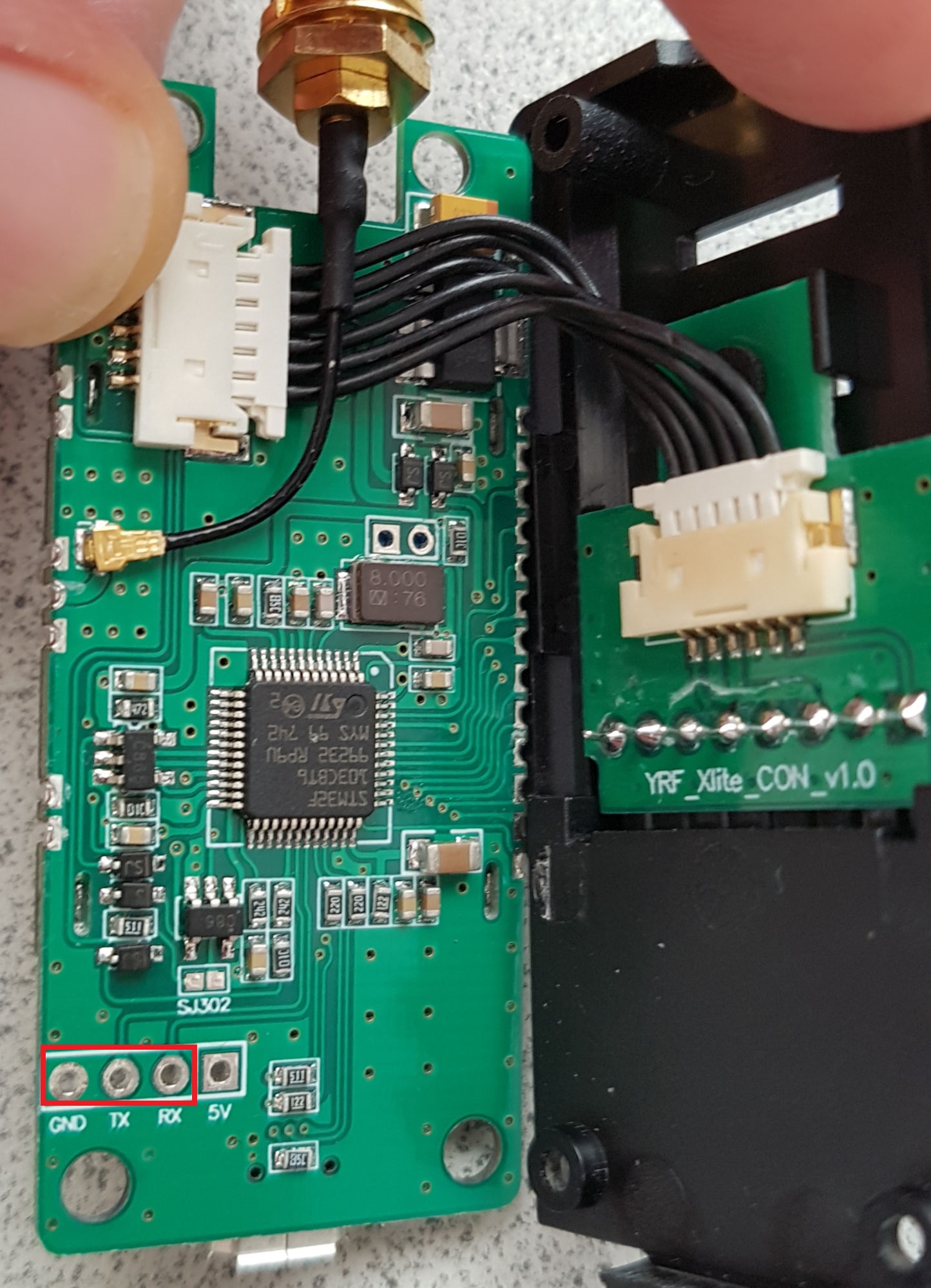
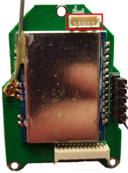
The header needs to be soldered onto the board as indicated by the red rectangle:
| **DIY Multiprotocol** | **Banggood 4-in-1** | **iRangeX IRX4 / IR4+** | **Jumper 4in1 1st gen** |
|:---:|:---:|:---:|:---:|
|
|
| [(example ebay link)](https://www.ebay.co.uk/itm/FTDI-USB-to-TTL-Serial-Converter-Adapter-FT232RL-Module-5V-and-3-3V-Arduino-ARM/231918152528) | [(example ebay link)](https://www.ebay.co.uk/itm/4x-826629-4-Pin-header-pin-strips-AMPMODU-MOD-II-male-PIN4-straight/192334571714) | [(example ebay link)](https://www.ebay.com/itm/5-PCS-Mini-Micro-ZH-1mm-2-6-Pin-JST-Connector-with-Wire-HI/183963001322) | [(example ebay link)](https://www.ebay.co.uk/itm/5-PAIRS-5-PIN-Micro-JST-GH-1-25-Connector-Plug-Socket-1-25mm-150mm-Cable/273110735668)
The USB-TTL adapter can be either FTDI or CH340G, as long as it works. It should have a switch or jumper to select 3.3V or 5V, which **must** be set to **3.3V**.
The header needs to be soldered onto the board as indicated by the red rectangle:
| **DIY Multiprotocol** | **Banggood 4-in-1** | **iRangeX IRX4 / IR4+** | **Jumper 4in1 1st gen** |
|:---:|:---:|:---:|:---:|
|  |
|  |
| 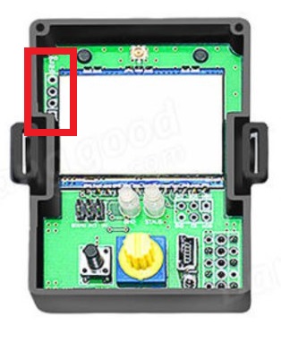 |
|  | **Vantac/URUAV Lite** | **iRangeX IRX4 Lite** | **Jumper T16 internal module** |
|:---:|:---:|:---:|
|
| **Vantac/URUAV Lite** | **iRangeX IRX4 Lite** | **Jumper T16 internal module** |
|:---:|:---:|:---:|
|  |
|  |
|  |
**Note:** The Banggood STM32 and T16 internal modules most likely already has the header pin in place.
## Option 1 - Update Firmware using Precompiled Binaries
If you don't need/want to customize the multi module firmware then you can use pre-compiled binaries available [here](https://github.com/pascallanger/DIY-Multiprotocol-TX-Module/releases).
**STM32 Builds (file names beginning with 'Multi-STM_')**
- All radio modules and protocols are included in all builds
- Files with TXFLASH in the name are built with a bootloader for flashing from a transmitter OR via the module's USB port (eg. Multi-STM_TXFLASH_INV-vX.X.X.XX.bin)
- Files with FTDI in the name are built without a bootloader for flashing using an FTDI adapter (eg. Multi-STM_FTDI_INV-vX.X.X.XX.bin)
- OpenTx/JumperTX version (files with OPENTX in the name) have the MULTI_TELEMETRY parameter enabled (eg. Multi-STM_TXFLASH_INV_OPENTX-vX.X.X.XX.bin or Multi-STM_FTDI_INV_OPENTX-vvX.X.X.XX.bin)
[Flash-Multi](https://github.com/benlye/flash-multi) is the recommended Windows utility for flashing pre-compiled firmware to any STM32-based Multiprotocol TX module. Firmware upload can be performed using the built-in USB connection or via an external FTDI adapter.
|
**Note:** The Banggood STM32 and T16 internal modules most likely already has the header pin in place.
## Option 1 - Update Firmware using Precompiled Binaries
If you don't need/want to customize the multi module firmware then you can use pre-compiled binaries available [here](https://github.com/pascallanger/DIY-Multiprotocol-TX-Module/releases).
**STM32 Builds (file names beginning with 'Multi-STM_')**
- All radio modules and protocols are included in all builds
- Files with TXFLASH in the name are built with a bootloader for flashing from a transmitter OR via the module's USB port (eg. Multi-STM_TXFLASH_INV-vX.X.X.XX.bin)
- Files with FTDI in the name are built without a bootloader for flashing using an FTDI adapter (eg. Multi-STM_FTDI_INV-vX.X.X.XX.bin)
- OpenTx/JumperTX version (files with OPENTX in the name) have the MULTI_TELEMETRY parameter enabled (eg. Multi-STM_TXFLASH_INV_OPENTX-vX.X.X.XX.bin or Multi-STM_FTDI_INV_OPENTX-vvX.X.X.XX.bin)
[Flash-Multi](https://github.com/benlye/flash-multi) is the recommended Windows utility for flashing pre-compiled firmware to any STM32-based Multiprotocol TX module. Firmware upload can be performed using the built-in USB connection or via an external FTDI adapter.

After a succesful flash your Module is now updated to the newer version firmware using the most common options. To change specific configured options you would need to use [Option-3](#option-3---compiling-and-updating-firmware), Compile using Arduino IDE and your desired upload method.
## Option 2 - Flash from TX
1. If you don't need/want to customize the multi module firmware then you can use pre-compiled binaries available [here](https://github.com/pascallanger/DIY-Multiprotocol-TX-Module/releases).
2. If you are compiling the firmware yourself in the Arduino environment with [Option-3](#option-3---compiling-and-updating-firmware), do the following to export the binary:
- Click **Sketch -> Export compiled Binary**, or press **Ctrl+Alt+S**
- Locate the file named **multi-stm-x.x.x.x.bin** in the **Multiprotocol source folder** folder (x.x.x.x is the multi version)
3. Follow the instructions [here](/docs/Flash_from_Tx.md) to upload the firmware using your radio
## Option 3 - Compiling and Updating Firmware
### Preparation
Multiprotocol firmware can be compiled and flashed with your customized firmware using the Arduino IDE. The guide below will walk you through all the steps in many details, don't be afraid by the length it is in fact simple!
### Install the Arduino IDE
1. Download and install the Arduino IDE. The currently supported Arduino version is 1.8.9, available for [Windows]( https://www.arduino.cc/download_handler.php?f=/arduino-1.8.9-windows.exe), [Mac OSX](https://www.arduino.cc/download_handler.php?f=/arduino-1.8.9-macosx.zip) and [Linux (64-bit)](https://www.arduino.cc/download_handler.php?f=/arduino-1.8.9-linux64.tar.xz)
1. It is recommended to upgrade Java to the [latest version](https://www.java.com/en/download/)
### Download the Multiprotocol source and open the project
1. Either
1. Download the zip file with the Multiprotocol module source code from [here](https://github.com/pascallanger/DIY-Multiprotocol-TX-Module/archive/master.zip) and unzip and copy the source code folder **Multiprotocol** to a location of your choosing, or
1. Clone the project using Git or Github Desktop, then
1. Double-click the **Multiprotocol.ino** file in the **Multiprotocol** folder to open the project in the Arduino IDE
### Install the Multi 4-in-1 board
1. Follow [these instructions](Arduino_IDE_Boards.md) to install the **Multi 4-in-1 STM32 Board** in the Arduino IDE
### Configure the Arduino IDE
1. Under **Tools -> Board** select **Multi 4-in-1 (STM32FC103)**
1. Under **Tools -> Debug Option** select **None**
### Configure the firmware
Make any changes you require to the firmware by editing the [_config.h](https://github.com/pascallanger/DIY-Multiprotocol-TX-Module/blob/master/Multiprotocol/_Config.h) file which is part of the source package you downloaded. All the firmware configuration is done in this one file which enables full customization and a must for any PPM application.
The STM32F103CB module has more than enough flash space for all the available protocols so, unlike the Atmega328p-based or STM32F103C8 module, it is not necessary to disable unused protocols.
You can still disable protocols if you wish, and you may also enable or disable other optional Multiprotocol features.
### Verify the firmware
To check that the program will compile correctly and fit in the STM32 click **Sketch -> Verify/Compile**, or press **Ctrl+R**.
If there are errors, carefully read it, go to the line number indicated and correct your typo. Arduino has different ways to indicate that the firmware is too big so check this by removing a large number of protocols and reenable them as you need.
If there are no errors and you see output like this:
```
Sketch uses 68564 bytes (52%) of program storage space. Maximum is 131072 bytes.
Global variables use 4064 bytes (19%) of dynamic memory, leaving 16416 bytes for local variables. Maximum is 20480 bytes.
```
You can proceed to the next step.
### Connect the module
#### USB port
Ensure that you [installed the necessary drivers](https://github.com/benlye/DIY-Multiprotocol-TX-Module/blob/doc-updates/docs/Arduino_IDE_Boards.md#install-device-drivers).
If your Multiprotocol module has a USB port, connect it to the computer. With the drivers installed your computer should detect the module as a COM port. If the device appears correctly (check in **Device Manager**) you can proceed to the next step and [upload the firmware](#upload-the-firmware). If not, you will need to flash your module one time using a USB-to-serial adapter (also known as an FTDI adapter).
**Note:** Some modules require external power in order for the USB port to work. If your module does not power on with USB power alone, install it in the transmitter and switch the transmitter on. It is generally safe for the module to recieve power from both USB and the transmitter.
#### USB-to-Serial adapter
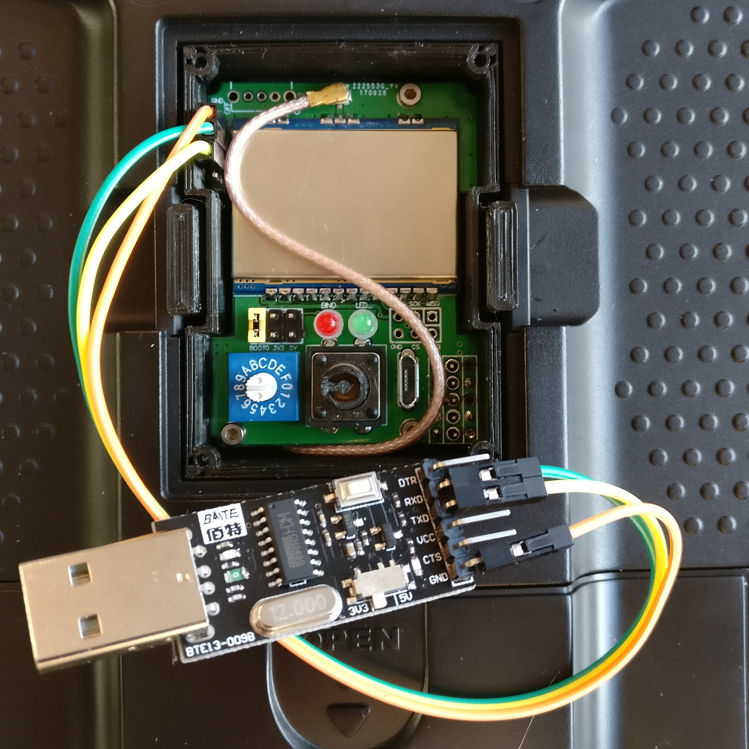
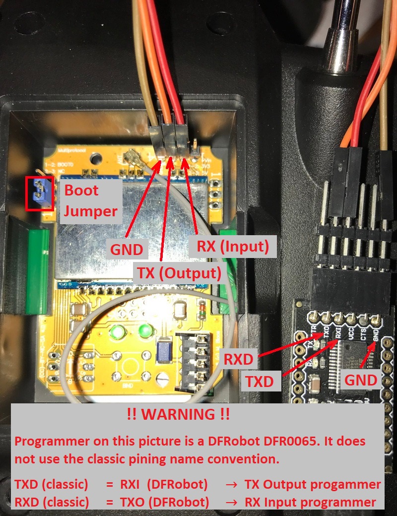
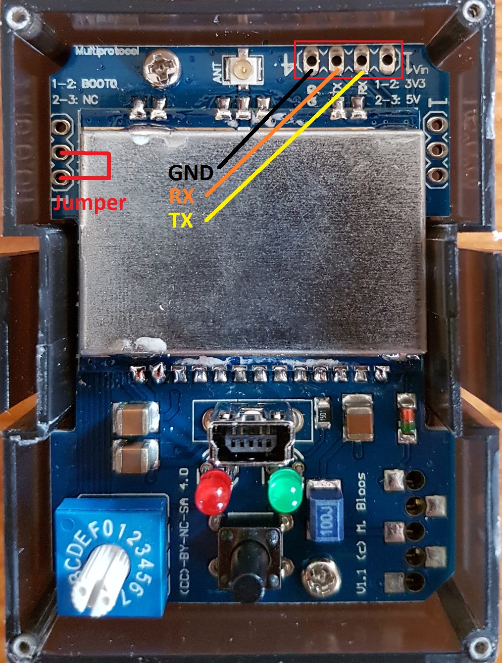
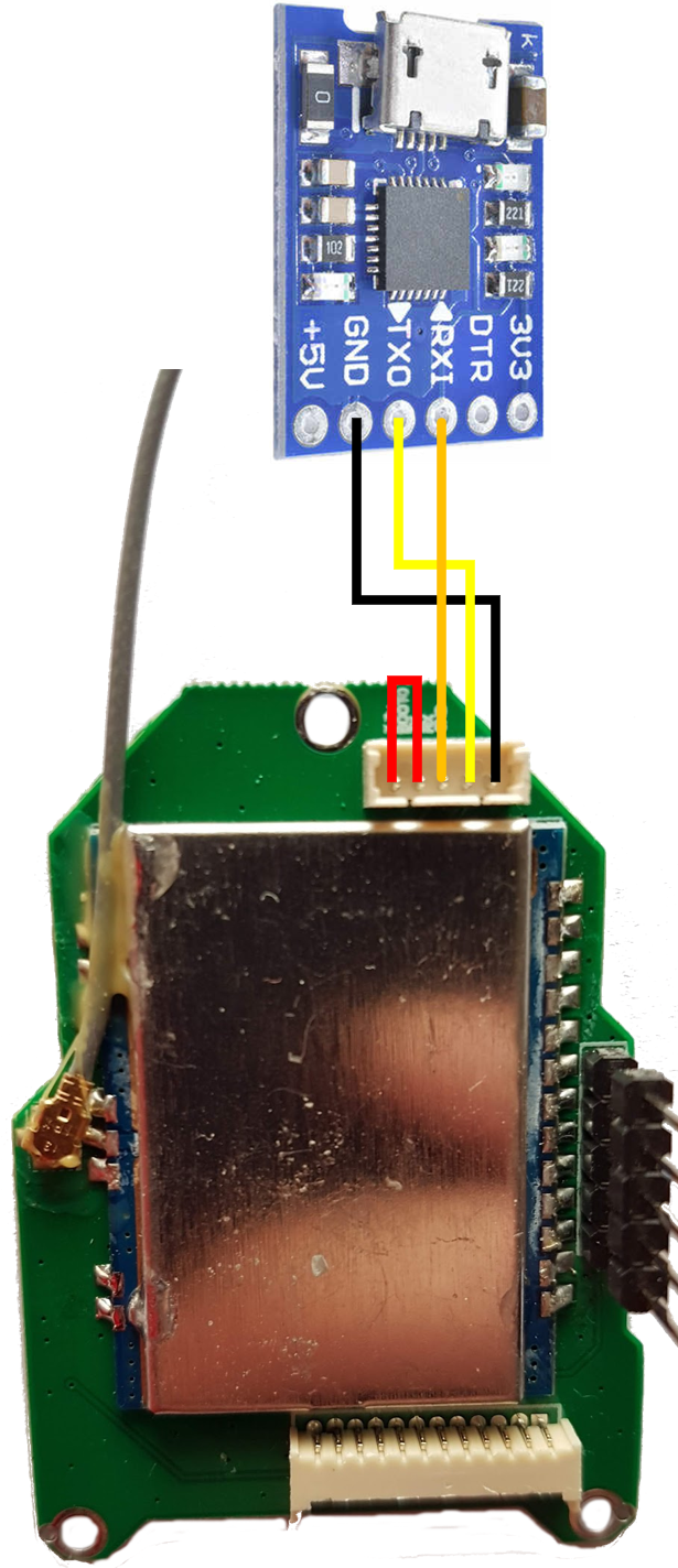
It is **strongly** recommended that you power your module from the transmitter when flashing it using a USB-to-serial adapater. This ensures that the module cannot be inadvertently supplied with 5V, which will damage the RF modules. This guide assumes that you will follow that advice, and instructs you to leave the V+ pin on the USB-to-TTL adapter disconnected. You may choose to ignore that advice at your own risk!
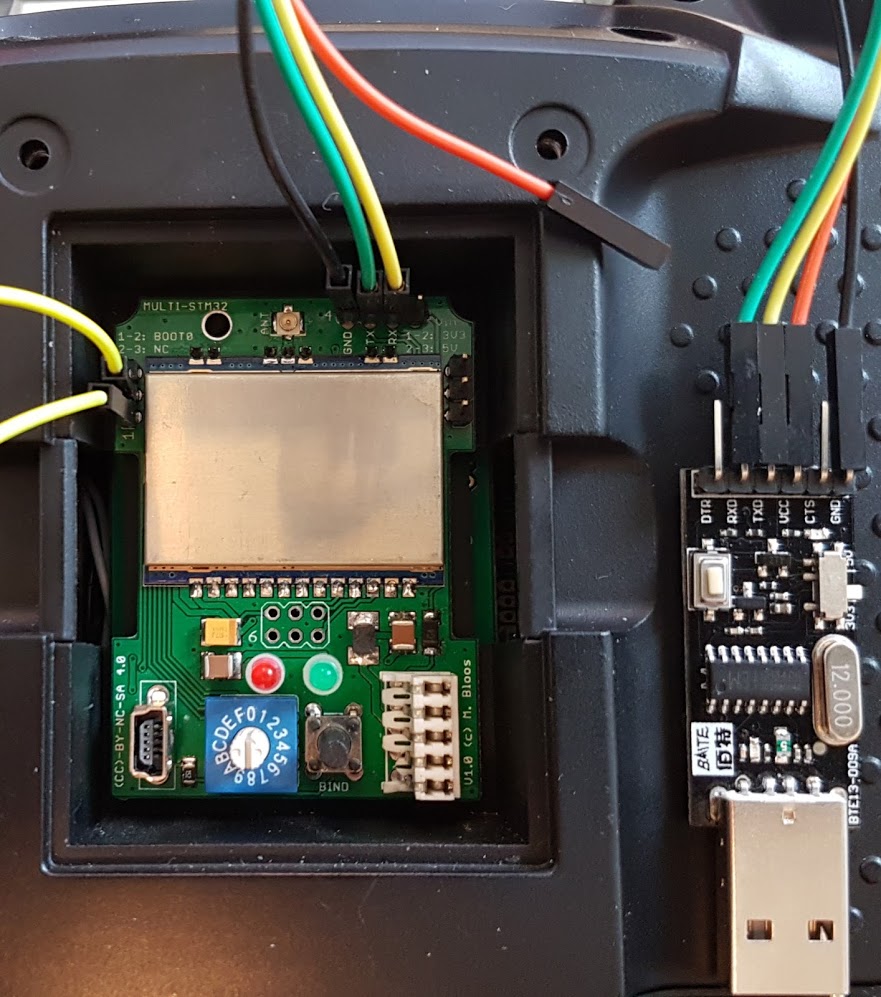
The wiring for the USB-to-TTL adapter is:
* USB-to-TTL TX pin <-> Module RX pin
* USB-to-TTL RX pin <-> Module TX pin
* USB-to-TTL GND pin <-> Module GND pin
* USB-to-TTL VC pin <-> **Not Connected**
**It is critical to ensure that the USB-to-TTL adapter is set to 3.3V**.
| **DIY Multiprotocol** | **Banggood 4-in-1** | **iRangeX IRX4** |
|:---:|:---:|:---:|
|  |
|  |
|  |
| **Jumper 4-in-1 1st gen** | **Jumper T16 internal module** |
|:---:|:---:|
|
|
| **Jumper 4-in-1 1st gen** | **Jumper T16 internal module** |
|:---:|:---:|
|  |
|  |
1. Put the module in the transmitter
1. Connect the USB-to-TTL adapter to the module as described above
1. Plug the USB-to-TTL adapter into the PC
1. In the Arduino IDE click **Tools -> Port** and choose the COM port which matches the USB-to-TTL adapter
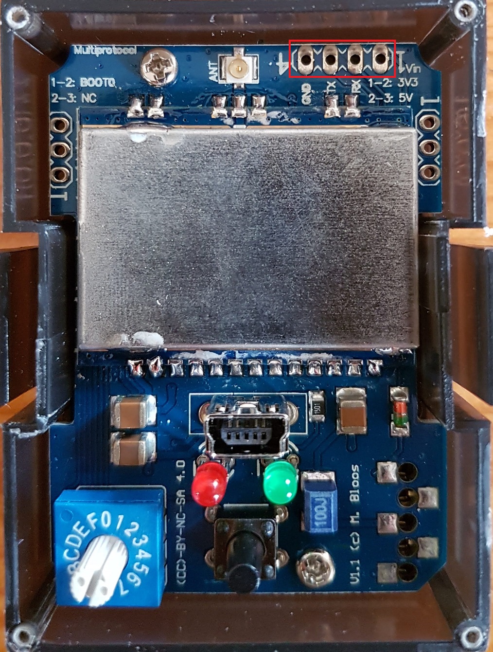
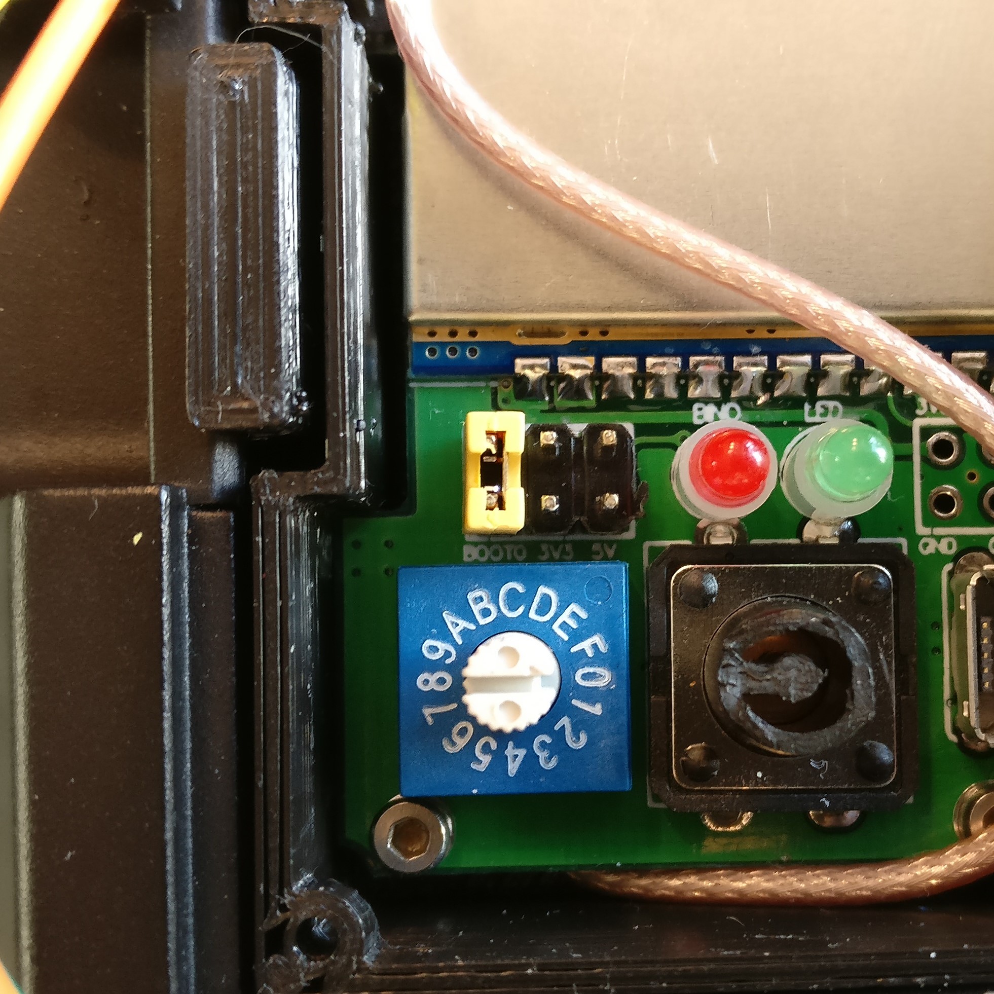
In order to flash the bootloader the **BOOT0** jumper must be installed connecting **BOOT0** to 3.3V. The location of **BOOT0** varies by hardware module.
| **DIY Multiprotocol** | **Banggood 4-in-1** | **iRangeX IRX4** | **iRangeX IRX4 Plus** | **Jumper 4-in-1 1st gen** |
|:---:|:---:|:---:|:---:|:---:|
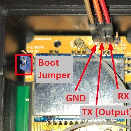
| Bridge pins 1 and 2 as shown by the yellow jumper wire. | Bridge the left-most pins of the 6-pin header as shown by the yellow jumper. | Bridge pins 1 and 2 as shown by the blue jumper. | Bridge the BOOT0 pin to the adjacent 3.3V pin as shown by the yellow jumper. If it doesn't work move the jumper to bridge the two left hand pins (BOOT0 and directly above). | Bridge pins 1 and 2 as shown by the red jumper wire. |
| |
|
1. Put the module in the transmitter
1. Connect the USB-to-TTL adapter to the module as described above
1. Plug the USB-to-TTL adapter into the PC
1. In the Arduino IDE click **Tools -> Port** and choose the COM port which matches the USB-to-TTL adapter
In order to flash the bootloader the **BOOT0** jumper must be installed connecting **BOOT0** to 3.3V. The location of **BOOT0** varies by hardware module.
| **DIY Multiprotocol** | **Banggood 4-in-1** | **iRangeX IRX4** | **iRangeX IRX4 Plus** | **Jumper 4-in-1 1st gen** |
|:---:|:---:|:---:|:---:|:---:|
| Bridge pins 1 and 2 as shown by the yellow jumper wire. | Bridge the left-most pins of the 6-pin header as shown by the yellow jumper. | Bridge pins 1 and 2 as shown by the blue jumper. | Bridge the BOOT0 pin to the adjacent 3.3V pin as shown by the yellow jumper. If it doesn't work move the jumper to bridge the two left hand pins (BOOT0 and directly above). | Bridge pins 1 and 2 as shown by the red jumper wire. |
| |  |
|  |
|  | |
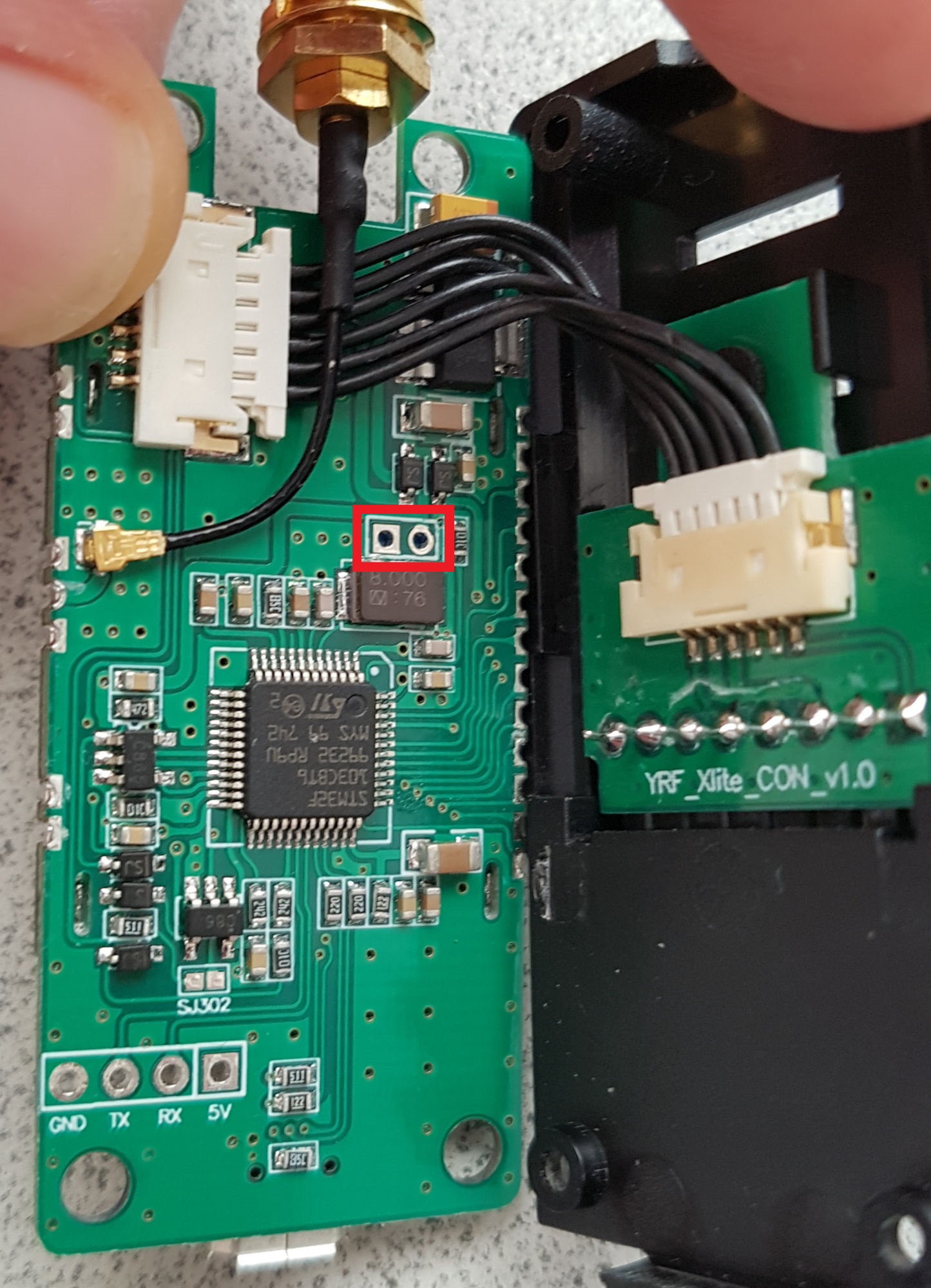
| **Vantac/URUAV Lite** | **iRangeX IRX4 Lite** | **Jumper T16 internal module** |
|:---:|:---:|:---:|
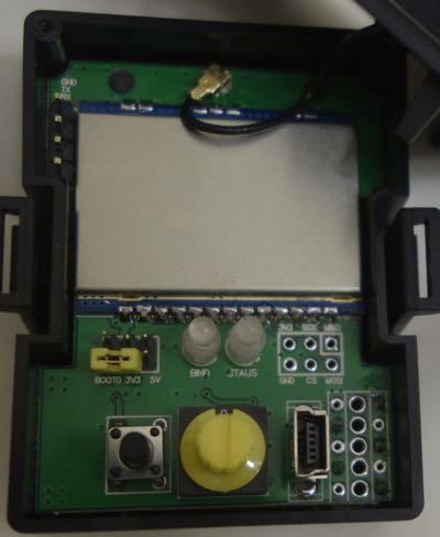
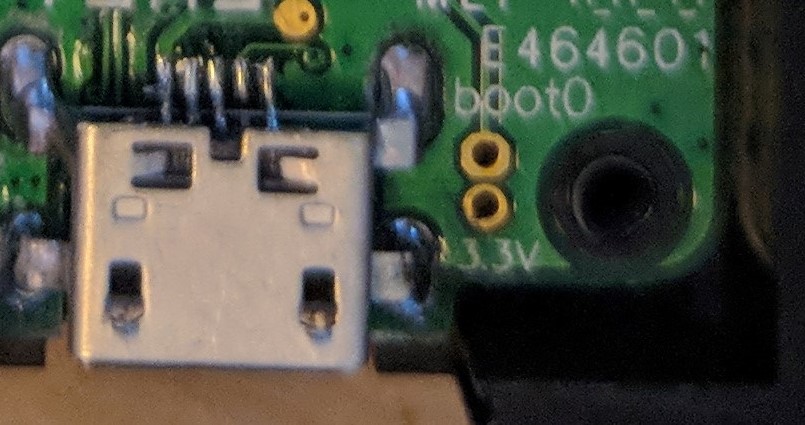
| Brdige the two pins next to the usb port labelled with Boot0 | Brdige the two indicated pins| Bridge BOOT0 and +3.3V in RED on the cabling |
|
| |
| **Vantac/URUAV Lite** | **iRangeX IRX4 Lite** | **Jumper T16 internal module** |
|:---:|:---:|:---:|
| Brdige the two pins next to the usb port labelled with Boot0 | Brdige the two indicated pins| Bridge BOOT0 and +3.3V in RED on the cabling |
|  |
|  | |
1. If on Linux, ensure you have permissions to access serial interfaces as described [here](https://github.com/benlye/DIY-Multiprotocol-TX-Module/blob/doc-updates/docs/Arduino_IDE_Boards.md#linux)
1. Install the **BOOT0** jumper as described above.
1. Switch on the transmitter
### Upload the firmware
1. In the Arduino IDE click **Sketch -> Upload**, or press **Ctrl+U**
## Option 4 - Flash via USB, using dfu-util (on Linux)
This upgrade method is only for modules that have USB connectors and
that have the ability to enter DFU mode when plugged into a Linux
machine.
[dfu-util](http://dfu-util.sourceforge.net/) is a command line tool that
can be used to write firmware to a processor that is in the DFU
state. Pre-built dfu-util packages are available for almost any Linux
distribution, so simply install the dfu-util package via your system's
package manager.
You now need to get your multimodule connected to your Linux machine
and make sure that it is in DFU mode. Usually the multimodule should
enter the DFU mode if you remove it from your radio and simply connect
it to your Linux machine via a _proper_ USB cable. Note: Some cheap,
loading USB cables sometimes have no data lines connected, and these
will no work.
Once your multimodule is connected, run the following command in order
to see if the DFU interface had been discovered:
```shell
# dfu-util -l -v
dfu-util 0.11
Copyright 2005-2009 Weston Schmidt, Harald Welte and OpenMoko Inc.
Copyright 2010-2021 Tormod Volden and Stefan Schmidt
This program is Free Software and has ABSOLUTELY NO WARRANTY
Please report bugs to http://sourceforge.net/p/dfu-util/tickets/
libusb version 1.0.26 (11724)
Found DFU: [1eaf:0003] ver=0201, devnum=69, cfg=1, intf=0, path="1-4", alt=2, name="STM32duino bootloader v1.0 Upload to Flash 0x8002000", serial="LLM 003"
Found DFU: [1eaf:0003] ver=0201, devnum=69, cfg=1, intf=0, path="1-4", alt=1, name="STM32duino bootloader v1.0 Upload to Flash 0x8005000", serial="LLM 003"
Found DFU: [1eaf:0003] ver=0201, devnum=69, cfg=1, intf=0, path="1-4", alt=0, name="STM32duino bootloader v1.0 ERROR. Upload to RAM not supported.", serial="LLM 003"
```
If you the above didn't succeed, your module is not in DFU mode and it
would not make any sense to continue.
Now that your Linux machine discovered the device with id, 1eaf:0003,
you can can start the update process, which will take around 8 to 10
seconds. Once done, your multimodule will be updated and you can
simply unplug it and start using it.
The example below, uses a pre-compiled binary available from
[here](https://github.com/pascallanger/DIY-Multiprotocol-TX-Module/releases).
```shell
# dfu-util -v -R -a 2 -d 1EAF:0003 -D mm-stm-serial-aetr-v1.3.3.14.bin
dfu-util 0.11
Copyright 2005-2009 Weston Schmidt, Harald Welte and OpenMoko Inc.
Copyright 2010-2021 Tormod Volden and Stefan Schmidt
This program is Free Software and has ABSOLUTELY NO WARRANTY
Please report bugs to http://sourceforge.net/p/dfu-util/tickets/
libusb version 1.0.26 (11724)
dfu-util: Warning: Invalid DFU suffix signature
dfu-util: A valid DFU suffix will be required in a future dfu-util release
Opening DFU capable USB device...
Device ID 1eaf:0003
Device DFU version 0110
DFU attributes: (0x03) bitCanDnload bitCanUpload
Detach timeout 255 ms
Claiming USB DFU Interface...
Setting Alternate Interface #2 ...
Determining device status...
DFU state(2) = dfuIDLE, status(0) = No error condition is present
DFU mode device DFU version 0110
Device returned transfer size 1024
Copying data from PC to DFU device
Download [=========================] 100% 118668 bytes
Download done.
Sent a total of 118668 bytes
DFU state(8) = dfuMANIFEST-WAIT-RESET, status(0) = No error condition is present
Resetting USB to switch back to runtime mode
Done!
```
NOTE: The above command was taken and adapted from
[here](https://github.com/benlye/flash-multi/blob/master/doc/Troubleshooting.md).
As you can see, the above process is really extremely straight
forward. You basically only need to have dfu-util installed and you need to
run one single command for updating your multimodule.
As a bonus, the dfu-util method could also be used under Mac or
Windows, as dfu-util binaries also exist for those operating systems.
# Troubleshooting
You can report your problem using the [GitHub issue](https://github.com/midelic/DIY-Multiprotocol-TX-Module/issues) system or go to the [Main thread on RCGROUPS](http://www.rcgroups.com/forums/showthread.php?t=2165676) to ask your question.
Please provide the following information:
- Multiprotocol code version
- STM32 version
- TX type
- Using PPM or Serial, if using er9x or ersky9x the version in use
- Different led status (multimodule and model)
- Explanation of the behavior and reproduction steps
| |
1. If on Linux, ensure you have permissions to access serial interfaces as described [here](https://github.com/benlye/DIY-Multiprotocol-TX-Module/blob/doc-updates/docs/Arduino_IDE_Boards.md#linux)
1. Install the **BOOT0** jumper as described above.
1. Switch on the transmitter
### Upload the firmware
1. In the Arduino IDE click **Sketch -> Upload**, or press **Ctrl+U**
## Option 4 - Flash via USB, using dfu-util (on Linux)
This upgrade method is only for modules that have USB connectors and
that have the ability to enter DFU mode when plugged into a Linux
machine.
[dfu-util](http://dfu-util.sourceforge.net/) is a command line tool that
can be used to write firmware to a processor that is in the DFU
state. Pre-built dfu-util packages are available for almost any Linux
distribution, so simply install the dfu-util package via your system's
package manager.
You now need to get your multimodule connected to your Linux machine
and make sure that it is in DFU mode. Usually the multimodule should
enter the DFU mode if you remove it from your radio and simply connect
it to your Linux machine via a _proper_ USB cable. Note: Some cheap,
loading USB cables sometimes have no data lines connected, and these
will no work.
Once your multimodule is connected, run the following command in order
to see if the DFU interface had been discovered:
```shell
# dfu-util -l -v
dfu-util 0.11
Copyright 2005-2009 Weston Schmidt, Harald Welte and OpenMoko Inc.
Copyright 2010-2021 Tormod Volden and Stefan Schmidt
This program is Free Software and has ABSOLUTELY NO WARRANTY
Please report bugs to http://sourceforge.net/p/dfu-util/tickets/
libusb version 1.0.26 (11724)
Found DFU: [1eaf:0003] ver=0201, devnum=69, cfg=1, intf=0, path="1-4", alt=2, name="STM32duino bootloader v1.0 Upload to Flash 0x8002000", serial="LLM 003"
Found DFU: [1eaf:0003] ver=0201, devnum=69, cfg=1, intf=0, path="1-4", alt=1, name="STM32duino bootloader v1.0 Upload to Flash 0x8005000", serial="LLM 003"
Found DFU: [1eaf:0003] ver=0201, devnum=69, cfg=1, intf=0, path="1-4", alt=0, name="STM32duino bootloader v1.0 ERROR. Upload to RAM not supported.", serial="LLM 003"
```
If you the above didn't succeed, your module is not in DFU mode and it
would not make any sense to continue.
Now that your Linux machine discovered the device with id, 1eaf:0003,
you can can start the update process, which will take around 8 to 10
seconds. Once done, your multimodule will be updated and you can
simply unplug it and start using it.
The example below, uses a pre-compiled binary available from
[here](https://github.com/pascallanger/DIY-Multiprotocol-TX-Module/releases).
```shell
# dfu-util -v -R -a 2 -d 1EAF:0003 -D mm-stm-serial-aetr-v1.3.3.14.bin
dfu-util 0.11
Copyright 2005-2009 Weston Schmidt, Harald Welte and OpenMoko Inc.
Copyright 2010-2021 Tormod Volden and Stefan Schmidt
This program is Free Software and has ABSOLUTELY NO WARRANTY
Please report bugs to http://sourceforge.net/p/dfu-util/tickets/
libusb version 1.0.26 (11724)
dfu-util: Warning: Invalid DFU suffix signature
dfu-util: A valid DFU suffix will be required in a future dfu-util release
Opening DFU capable USB device...
Device ID 1eaf:0003
Device DFU version 0110
DFU attributes: (0x03) bitCanDnload bitCanUpload
Detach timeout 255 ms
Claiming USB DFU Interface...
Setting Alternate Interface #2 ...
Determining device status...
DFU state(2) = dfuIDLE, status(0) = No error condition is present
DFU mode device DFU version 0110
Device returned transfer size 1024
Copying data from PC to DFU device
Download [=========================] 100% 118668 bytes
Download done.
Sent a total of 118668 bytes
DFU state(8) = dfuMANIFEST-WAIT-RESET, status(0) = No error condition is present
Resetting USB to switch back to runtime mode
Done!
```
NOTE: The above command was taken and adapted from
[here](https://github.com/benlye/flash-multi/blob/master/doc/Troubleshooting.md).
As you can see, the above process is really extremely straight
forward. You basically only need to have dfu-util installed and you need to
run one single command for updating your multimodule.
As a bonus, the dfu-util method could also be used under Mac or
Windows, as dfu-util binaries also exist for those operating systems.
# Troubleshooting
You can report your problem using the [GitHub issue](https://github.com/midelic/DIY-Multiprotocol-TX-Module/issues) system or go to the [Main thread on RCGROUPS](http://www.rcgroups.com/forums/showthread.php?t=2165676) to ask your question.
Please provide the following information:
- Multiprotocol code version
- STM32 version
- TX type
- Using PPM or Serial, if using er9x or ersky9x the version in use
- Different led status (multimodule and model)
- Explanation of the behavior and reproduction steps