# Flashing, Compiling and Programming (STM32)
Multiprotocol firmware can be either flashed with a precompiled binary (Option-1) or compile/upload your customized firmware using the Arduino IDE (Option-2).
**These instructions are for the STM32 version of the Multiprotocol module.** If you are Compling for the Arduino ATmega328p version of the Multiprotocol Module please go to the dedicated [ATmega328](Compiling.md) page.
## Index
1. [Tools Required](#tools-required)
1. [Option-1 Update firmware using precompiled binaries](#option-1-update-firmware-using-precompiled-binaries)
1. [Option-2 Compiling and updating firmware](#option-2-compiling-and-updating-firmware)
1. [Preparation](#preparation)
1. [Install the Arduino IDE](#install-the-arduino-ide)
1. [Download the Multiprotocol source and open the project](#download-the-multiprotocol-source-and-open-the-project)
1. [Install the Multi 4-in-1 board](#install-the-multi-4-in-1-board)
1. [Configure the Arduino IDE](#configure-the-arduino-ide)
1. [Configure the firmware](#configure-the-firmware)
1. [Verify the firmware](#verify-the-firmware)
1. [Preparing to upload the firmware](#preparing-to-upload-the-firmware)
1. [Select an upload method](#select-an-upload-method)
1. [Upload via Serial inc. Bootloader (FTDI)](#upload-via-serial-inc-bootloader-ftdi)
1. [Flash from TX](#flash-from-tx)
1. [Upload via USB](#upload-via-usb)
1. [Install the Maple USB Drivers](#install-the-maple-usb-drivers)
1. [Upload the firmware](#upload-the-firmware)
1. [Troubleshooting](#troubleshooting)
## Tools required
Tools are only required if a multi module does not have a USB port, a working bootloader or an integrated FTDI adapter:
* The latest iRangeX IRX4+ modules most likely already have the USB Bootloader flashed on it. You therefore don't need the FTDI adapter below and don't need to open your module to flash it.
* The latest jumper modules have an integrated FTDI appearing as a CP2102 device on the computer. You therefore don't need the FTDI adapter below and don't need to open your module to flash it.
* The Vantac MPM Lite module already has the USB Bootloader flashed on it. You therefore don't need the FTDI adapter below and don't need to open your module to flash it. **Modules' bootloader however might not be booting everytime depending on the radio, if this is the case you need to upgrade it.**
You are still unsure if your module can be flashed without tools or opening it? Here is how to quickly check:
* Power off the TX
* Connect a USB cable to the module, if the module does not have a USB port then you must open the module to flash it using an external FTDI
* Connect the cable to the PC and power on the the TX
* If the PC does not complain about a none working device being plugged then you are good to upgrade via USB directly without the need of any tools or opening the module.
Your multi module is not USB upgradable ready, here is what you need:
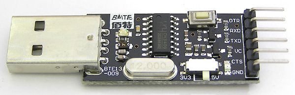
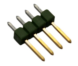
| **3.3V USB-TTL Adapter** | **4-pin Serial Programming Header** |
|:---:|:--:|
|  |
|  | [(example ebay link)](https://www.ebay.co.uk/itm/FTDI-USB-to-TTL-Serial-Converter-Adapter-FT232RL-Module-5V-and-3-3V-Arduino-ARM/231918152528) | [(example ebay link)](https://www.ebay.co.uk/itm/4x-826629-4-Pin-header-pin-strips-AMPMODU-MOD-II-male-PIN4-straight/192334571714) |
The USB-TTL adapter can be either FTDI or CH340G, as long as it works. It should have a switch or jumper to select 3.3V or 5V, which **must** be set to **3.3V**.
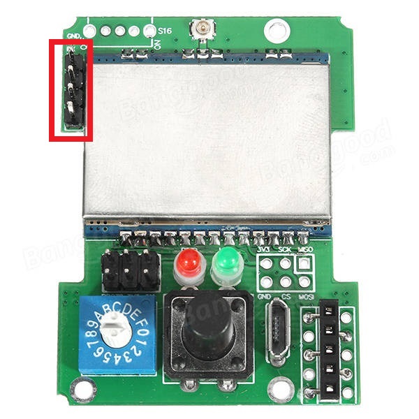
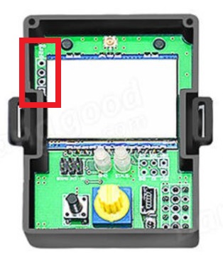
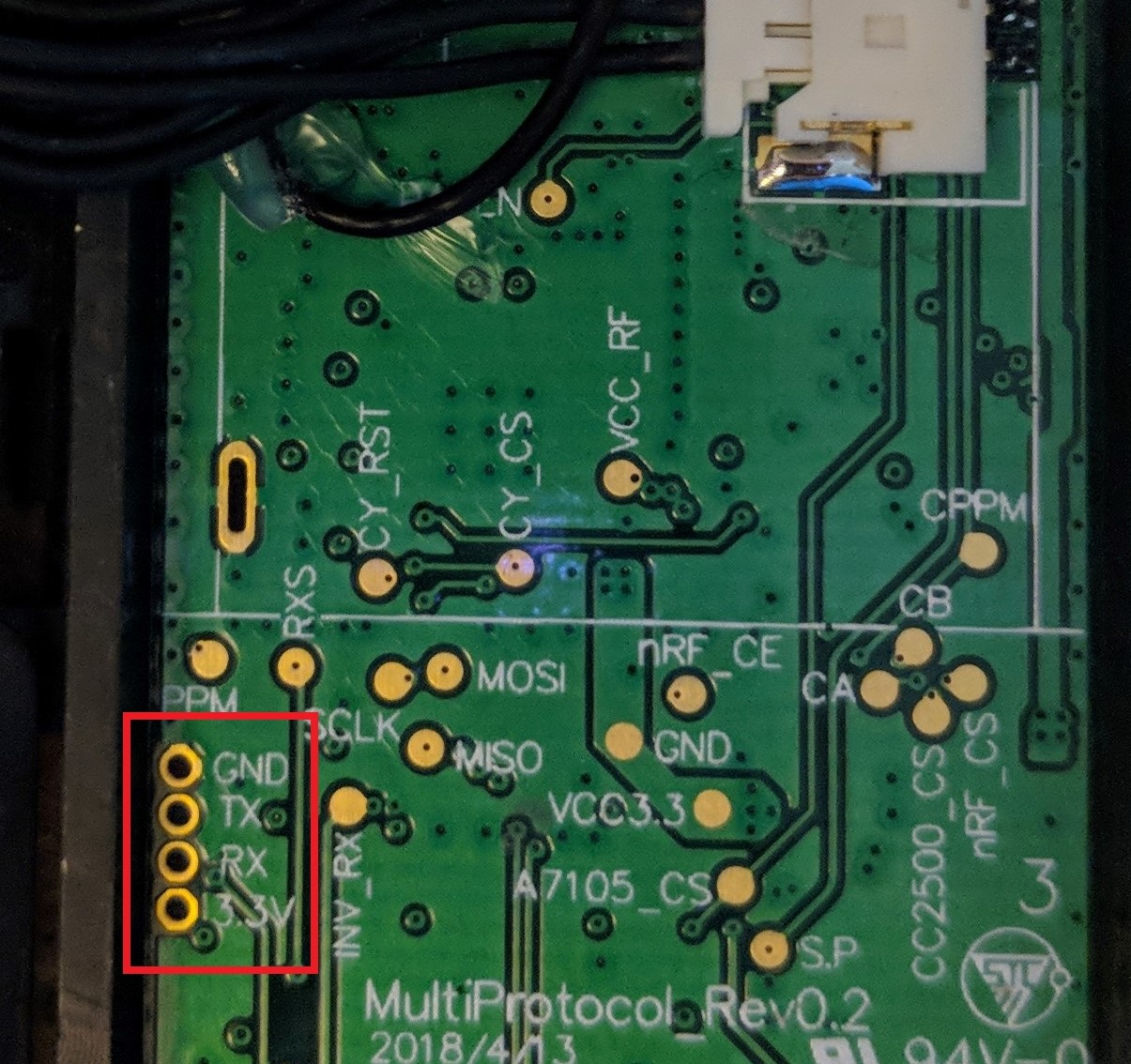
The 4-pin header needs to be soldered onto the board as indicated by the red rectangle:
| **DIY Multiprotocol** | **Banggood 4-in-1** | **iRangeX IRX4 Plus** | **Jumper** | **MPM Lite** |
|:---:|:---:|:---:|:---:|:---:|
|
| [(example ebay link)](https://www.ebay.co.uk/itm/FTDI-USB-to-TTL-Serial-Converter-Adapter-FT232RL-Module-5V-and-3-3V-Arduino-ARM/231918152528) | [(example ebay link)](https://www.ebay.co.uk/itm/4x-826629-4-Pin-header-pin-strips-AMPMODU-MOD-II-male-PIN4-straight/192334571714) |
The USB-TTL adapter can be either FTDI or CH340G, as long as it works. It should have a switch or jumper to select 3.3V or 5V, which **must** be set to **3.3V**.
The 4-pin header needs to be soldered onto the board as indicated by the red rectangle:
| **DIY Multiprotocol** | **Banggood 4-in-1** | **iRangeX IRX4 Plus** | **Jumper** | **MPM Lite** |
|:---:|:---:|:---:|:---:|:---:|
|  |
|  |
|  |
|  |
|  **Note:** The Banggood STM32 module most likely already has the header pin in place.
## Option-1 Update Firmware using Precompiled Binaries
If you don't need/want to customize the multi module firmware then you can use pre-compiled binaries available [here](https://github.com/pascallanger/DIY-Multiprotocol-TX-Module/releases).
**STM32 Builds (file names beginning with 'Multi-STM_')
- All radio modules and protocols are included in all builds
- Files with TXFLASH in the name are built with a bootloader for flashing from a transmitter OR via the module's USB port (eg. Multi-STM_TXFLASH_INV-vX.X.X.XX.bin)
- Files with FTDI in the name are built without a bootloader for flashing using an FTDI adapter (eg. Multi-STM_FTDI_INV-vX.X.X.XX.bin)
- OpenTx/JumperTX version (files with OPENTX in the name) have the MULTI_TELEMETRY parameter enabled (eg. Multi-STM_TXFLASH_INV_OPENTX-vX.X.X.XX.bin or Multi-STM_FTDI_INV_OPENTX-vvX.X.X.XX.bin)
[Flash-Multi](https://github.com/benlye/flash-multi) is the recommended Windows utility for flashing pre-compiled firmware to any STM32-based Multiprotocol TX module. Firmware upload can be performed using the built-in USB connection or via an external FTDI adapter.
**Note:** The Banggood STM32 module most likely already has the header pin in place.
## Option-1 Update Firmware using Precompiled Binaries
If you don't need/want to customize the multi module firmware then you can use pre-compiled binaries available [here](https://github.com/pascallanger/DIY-Multiprotocol-TX-Module/releases).
**STM32 Builds (file names beginning with 'Multi-STM_')
- All radio modules and protocols are included in all builds
- Files with TXFLASH in the name are built with a bootloader for flashing from a transmitter OR via the module's USB port (eg. Multi-STM_TXFLASH_INV-vX.X.X.XX.bin)
- Files with FTDI in the name are built without a bootloader for flashing using an FTDI adapter (eg. Multi-STM_FTDI_INV-vX.X.X.XX.bin)
- OpenTx/JumperTX version (files with OPENTX in the name) have the MULTI_TELEMETRY parameter enabled (eg. Multi-STM_TXFLASH_INV_OPENTX-vX.X.X.XX.bin or Multi-STM_FTDI_INV_OPENTX-vvX.X.X.XX.bin)
[Flash-Multi](https://github.com/benlye/flash-multi) is the recommended Windows utility for flashing pre-compiled firmware to any STM32-based Multiprotocol TX module. Firmware upload can be performed using the built-in USB connection or via an external FTDI adapter.

After a succesful flash your Module is now updated to the newer version firmware using the most common options. To change specific configured options you would need to use Option-2, Compile and flash update using Arduino IDE.
# Option-2 Compiling and Updating Firmware
## Preparation
Multiprotocol firmware can be compiled and uploaded with your customized firmware using the Arduino IDE. The guide below will walk you through all the steps in many details, don't be afraid by the length it is in fact simple!
### Install the Arduino IDE
1. Download and install the Arduino IDE. The currently supported Arduino version is 1.8.5, available for [Windows]( https://www.arduino.cc/download_handler.php?f=/arduino-1.8.5-windows.exe), [Mac OSX](https://www.arduino.cc/download_handler.php?f=/arduino-1.8.5-macosx.zip) and [Linux (64-bit)](https://www.arduino.cc/download_handler.php?f=/arduino-1.8.5-linux64.tar.xz)
1. It is recommended to upgrade Java to the [latest version](https://www.java.com/en/download/)
### Download the Multiprotocol source and open the project
1. Either
1. Download the zip file with the Multiprotocol module source code from [here](https://github.com/pascallanger/DIY-Multiprotocol-TX-Module/archive/master.zip) and unzip and copy the source code folder **Multiprotocol** to a location of your choosing, or
1. Clone the project using Git or Github Desktop, then
1. Double-click the **Multiprotocol.ino** file in the **Multiprotocol** folder to open the project in the Arduino IDE
**Important note for Windows users:** You must download or unzip the Multiprotocol source in a folder which has no spaces in the path. If you have spaces in your username **do not** use a sub-folder of your user directory. This is due to a [bug in the Arduino IDE](https://github.com/arduino/arduino-builder/issues/316), caused by an [issue in Go](https://github.com/golang/go/issues/17149).
### Install the Multi 4-in-1 board
1. Follow [these instructions](Arduino_IDE_Boards.md) to install the **Multi 4-in-1 STM32 Board** in the Arduino IDE
### Configure the Arduino IDE
1. Under **Tools -> Board** select **Multi 4-in-1 (STM32FC103)**
1. Under **Tools -> Upload method** select **Auto Detect (USB or Serial)** <- more details on this subject later on
1. Under **Tools -> Programmer** select **stm32flash (FTDI)**
## Configure the firmware
The STM32 module has more than enough flash space for all the available protocols so, unlike the Atmega328p-based module, it is not necessary to disable unused protocols.
You can still disable protocols if you wish, and you may also enable or disable other optional Multiprotocol features.
## Verify the firmware
To check that the program will compile correctly and fit in the STM32 click **Sketch -> Verify/Compile**, or press **Ctrl+R**.
If there are errors, carefully read it, go to the line number indicated and correct your typo.
If there are no errors and you see output like this:
```
Sketch uses 68564 bytes (52%) of program storage space. Maximum is 131072 bytes.
Global variables use 4064 bytes (19%) of dynamic memory, leaving 16416 bytes for local variables. Maximum is 20480 bytes.
```
You can proceed to the next step.
## Preparing to upload the firmware
If you have already burnt the bootloader, and are simply recompiling firmware to re-flash using your TX or USB cable, you can skip this step and go straight to [Flash from TX](#flash-from-tx) or [Upload via USB](#upload-via-usb).
STM modules, until now, do not come with a preloaded bootloader which makes the USB port unusable and discovered by a computer as unknown device. **For the first time use, you must use the upload method Upload via Serial inc. Bootloader (FTDI)** independently of what method you wish to use in future.
The latest Jumper 4-in-1 modules come with a USB port but it's in fact a built in FTDI appearing on the computer as a CP2102 serial device. You should use the method **Upload via Serial inc. Bootloader** instead of Upload via USB. 'Flash from TX' is supported once the bootloader is installed.
### Select an Upload Method
There are a total of five firmware upload methods to an STM32 module:
* **Flash from TX** - uses the bootloader mode of radios running ersky9x or OpenTX to upload the firmware. The radio needs to run the latest bootloader with the Multi Flash app.
* **Auto Detect (USB or Serial)** - Detects automatically if the upload method is USB or Serial. You need to configure the correct COM port in the IDE which is created when plugging the module.
* **Upload via USB** - uses the USB upload method through the USB plug of the module. It requires the presence of a bootloader in the module.
* **Upload via Serial inc. Bootloader (FTDI)** - uses the serial interface of the module via a USB-to-TTL adapter to install the bootloader and firmware.
* **Upload via Serial (FTDI)** - uses the serial interface of the module via a USB-to-TTL adapter to install the firmware.
You will most likely use only once on a brand new module the **Upload via Serial inc. Bootloader (FTDI)** method to load the bootloader+firmware. Any successive updates will be done using either **Auto Detect (USB or Serial)** or **Flash from TX** depending on your preference.
1. Under **Tools -> Upload Method** select an upload method
The rest of this process will vary depending on the upload method you selected.
## Upload via Serial inc. Bootloader (FTDI)
It is **strongly** recommended that you power your module from the transmitter when flashing it. This ensures that the module cannot be inadvertently supplied with 5V, which will damage the RF modules. This guide assumes that you will follow that advice, and instructs you to leave the V+ pin on the USB-to-TTL adapter disconnected. You may choose to ignore that advice at your own risk!
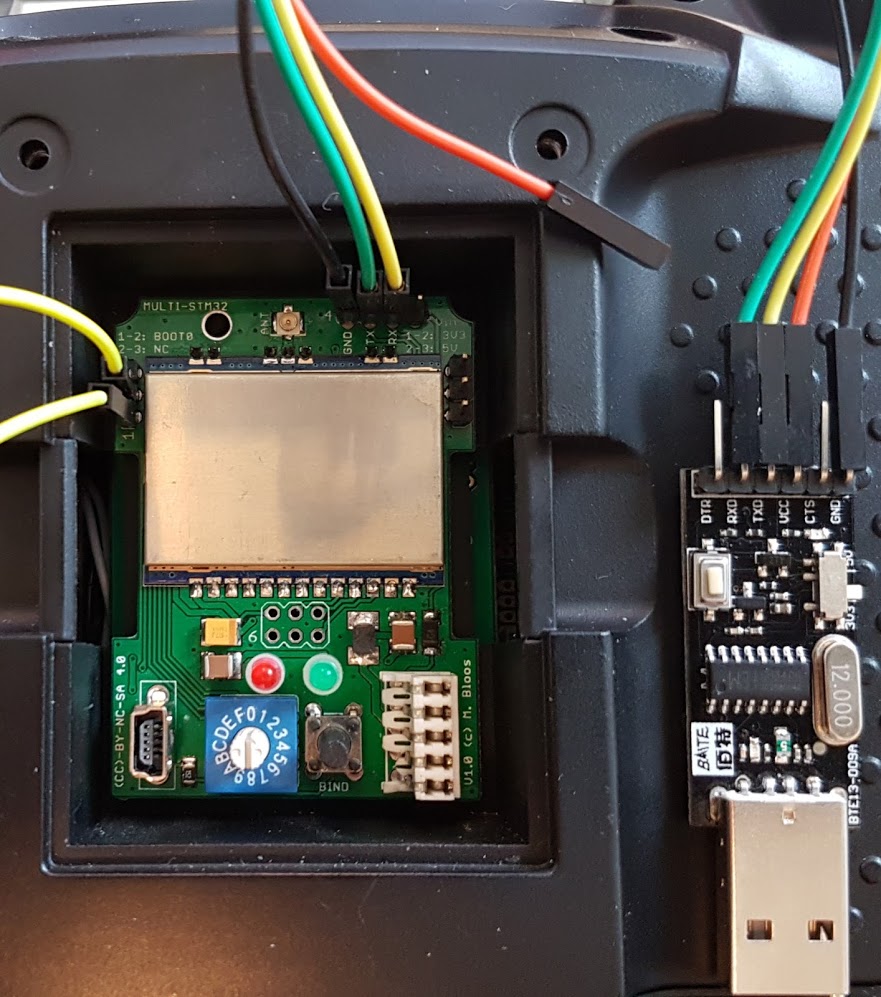
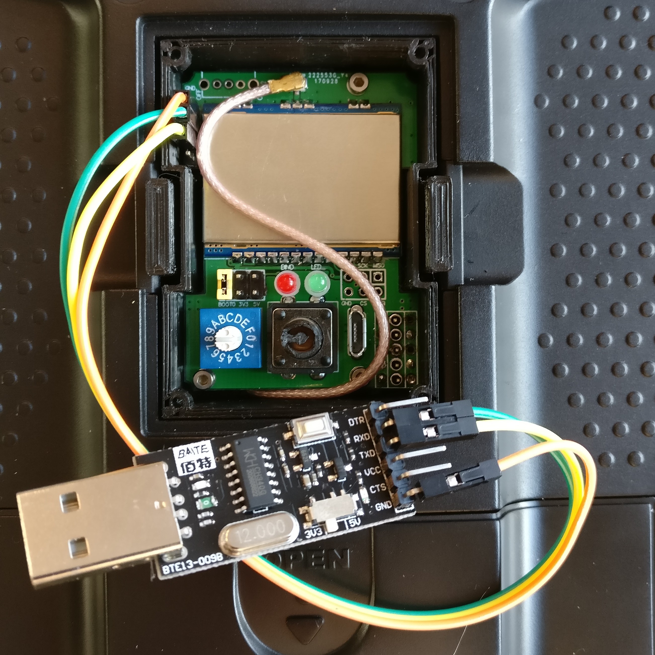
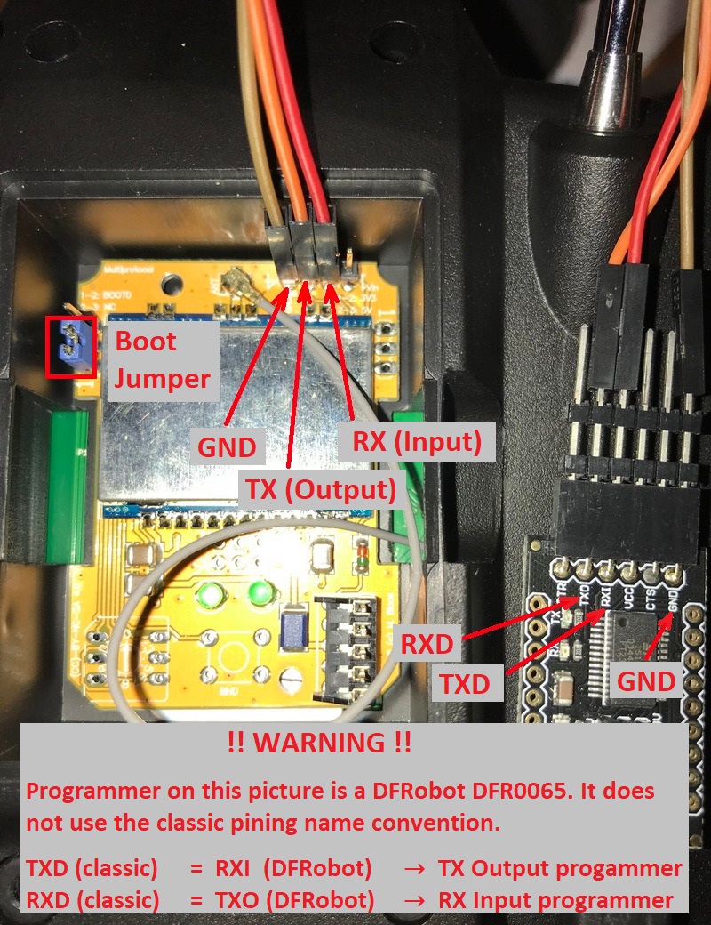
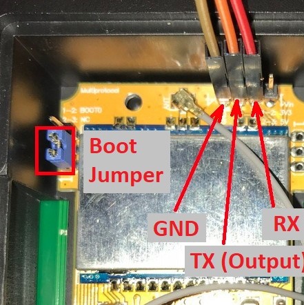
The wiring for the USB-to-TTL adapter is:
* USB-to-TTL TX pin <-> Module RX pin
* USB-to-TTL RX pin <-> Module TX pin
* USB-to-TTL GND pin <-> Module GND pin
* USB-to-TTL VC pin <-> **Not Connected**
**It is critical to ensure that the USB-to-TTL adapter is set to 3.3V**.
| **DIY Multiprotocol** | **Banggood 4-in-1** | **iRangeX IRX4** | **Jumper 4-in-1** |
|:---:|:---:|:---:|:---:|
|  |
|  |
|  |
| 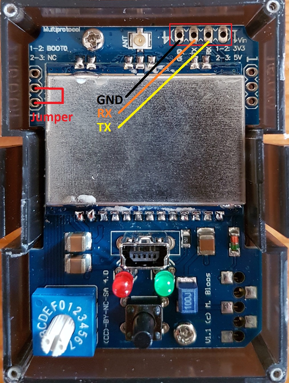 |
1. Put the module in the transmitter
1. Connect the USB-to-TTL adapter to the module as described above
1. Plug the USB-to-TTL adapter into the PC
1. In the Arduino IDE click **Tools -> Port** and choose the COM port which matches the USB-to-TTL adapter
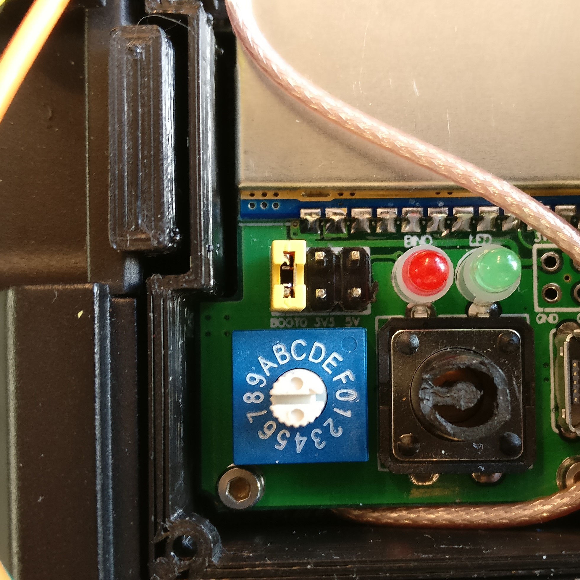
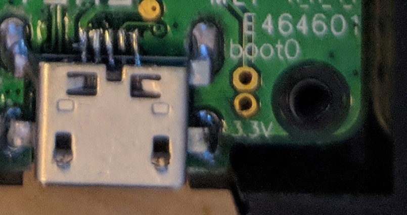
In order to flash the bootloader the **BOOT0** jumper must be installed connecting **BOOT0** to 3.3V. The location of **BOOT0** varies by hardware module. The latest Jumper modules with an intergrated FTDI do not need the BOOT0 jumper.
| **DIY Multiprotocol** | **Banggood 4-in-1** | **iRangeX IRX4** | **iRangeX IRX4 Plus** | **Jumper 4-in-1** | **Vantac MPM Lite** |
|:---:|:---:|:---:|:---:|:---:|:---:|
| Bridge pins 1 and 2 as shown by the yellow jumper wire. | Bridge the left-most pins of the 6-pin header as shown by the yellow jumper. | Bridge pins 1 and 2 as shown by the blue jumper. | Bridge the BOOT0 pin to the adjacent 3.3V pin as shown by the yellow jumper. If it doesn't work move the jumper to bridge the two left hand pins (BOOT0 and directly above). | Bridge pins 1 and 2 as shown by the red jumper wire. | Brdige the two pins next to the usb port labelled with Boot0 |
| |
|
1. Put the module in the transmitter
1. Connect the USB-to-TTL adapter to the module as described above
1. Plug the USB-to-TTL adapter into the PC
1. In the Arduino IDE click **Tools -> Port** and choose the COM port which matches the USB-to-TTL adapter
In order to flash the bootloader the **BOOT0** jumper must be installed connecting **BOOT0** to 3.3V. The location of **BOOT0** varies by hardware module. The latest Jumper modules with an intergrated FTDI do not need the BOOT0 jumper.
| **DIY Multiprotocol** | **Banggood 4-in-1** | **iRangeX IRX4** | **iRangeX IRX4 Plus** | **Jumper 4-in-1** | **Vantac MPM Lite** |
|:---:|:---:|:---:|:---:|:---:|:---:|
| Bridge pins 1 and 2 as shown by the yellow jumper wire. | Bridge the left-most pins of the 6-pin header as shown by the yellow jumper. | Bridge pins 1 and 2 as shown by the blue jumper. | Bridge the BOOT0 pin to the adjacent 3.3V pin as shown by the yellow jumper. If it doesn't work move the jumper to bridge the two left hand pins (BOOT0 and directly above). | Bridge pins 1 and 2 as shown by the red jumper wire. | Brdige the two pins next to the usb port labelled with Boot0 |
| |  |
|  |
|  | |
| |  |
1. If on Linux, ensure you have permissions to access serial interfaces as described in [Install the Maple USB drivers](#install-the-maple-usb-drivers)
1. Install the **BOOT0** jumper as described above.
1. Switch on the transmitter
1. Verify that you have selected the upload method **Upload via Serial inc. Bootloader (FTDI)** under **Tools -> Upload Method**
1. Verify that you have selected **stm32flash (FTDI)** as the programmer under **Tools -> Programmer**
1. Verify that the USB-to-TTL adapter is correctly connected to your module and you have selected the correct port under **Tools -> Port**
1. In the Arduino IDE click **Sketch -> Upload**, or press **Ctrl+U**
Output will look similar to this:
```
C:\Users\blye\AppData\Local\Arduino15\packages\multi4in1\hardware\STM32F1\1.0.0/tools/win/serial_upload.bat COM4 0x0 C:\Users\blye\AppData\Local\Arduino15\packages\multi4in1\hardware\STM32F1\1.0.0/bootloaders/Multi4in1/StmMultiUSB.bin
stm32flash -v -g 0x0 -b 57600 -w C:\Users\blye\AppData\Local\Arduino15\packages\multi4in1\hardware\STM32F1\1.0.0\bootloaders\Multi4in1\StmMultiUSB.bin COM4
stm32flash 0.4
http://stm32flash.googlecode.com/
Using Parser : Raw BINARY
Interface serial_w32: 57600 8E1
Version : 0x22
Option 1 : 0x00
Option 2 : 0x00
Device ID : 0x0410 (Medium-density)
- RAM : 20KiB (512b reserved by bootloader)
- Flash : 128KiB (sector size: 4x1024)
- Option RAM : 16b
- System RAM : 2KiB
Write to memory
Erasing memory
Wrote and verified address 0x08000100 (3.56%)
Wrote and verified address 0x08000200 (7.13%)
...
Wrote and verified address 0x08001c00 (99.78%)
Wrote and verified address 0x08001c10 (100.00%) Done.
Starting execution at address 0x08000000... done.
```
Assuming the process is successful:
1. Power off the transmitter
1. Remove the **BOOT0** jumper
1. Disconnect the USB-to-TTL adapter
1. Your module is ready to use, enjoy!!!
## Flash from TX
1. The MPM module must have a recent bootloader installed
1. Click **Tools -> Upload method -> Flash from TX**
1. Click **Sketch -> Export compiled Binary**, or press **Ctrl+Alt+S**
1. Locate the file named **multi-stm-x.x.x.x.bin** in the **Multiprotocol source folder** folder (x.x.x.x is the multi version)
1. Follow the instructions [here](/docs/Flash_from_Tx.md) to upload the firmware using your radio
1. Once done your module is ready to be used
## Upload via USB
In order for the module to be correctly identified it is necessary and only once to do some operations based on your operating system.
### Install the Maple USB drivers
##### Windows 7 or newer:
1. Open the folder where you unzipped or cloned the Multiprotocol project
1. Browse to **\BootLoaders\Boards\Windows**
1. Run **install-drivers.bat**
1. Follow the prompts to install the two drivers
##### Windows XP or older
1. Download and install the legacy Windows XP drivers from [here](https://github.com/rogerclarkmelbourne/Arduino_STM32/tree/master/drivers/win/win_xp_legacy)
**NOTE:** If you have installed the drivers and your module is not detected as a Maple device it most likely does not have a USB bootloader installed. Ready-made modules from Banggood **do not** come with a USB bootloader installed. You will need to follow the procedure to [Burn a USB bootloader](#upload-via-serial-inc-bootloader-ftdi) before you can upload firmware.
##### Mac OS X
Uploading via USB requires the [libusb library](https://libusb.info/) to be installed. The easiest way to install the library is using the [Homebrew package manager for macOS](https://brew.sh/) by executing the two lines given below in a Terminal.
Install Homebrew:
/usr/bin/ruby -e "$(curl -fsSL https://raw.githubusercontent.com/Homebrew/install/master/install)"
Once Homebrew is installed, use it to install libusb:
brew install libusb
##### Linux (64-bit)
To execute any of the following commands you should use a Terminal (shell) with the current directory set to the location where you cloned or unpacked this project.
You can do this by navigating to the project folder in the Files application then right clicking and selecting "Open in Terminal" from the menu that appears. This will open a Terminal where you will enter the commands indicated below.
If you are using Ubuntu 16.04 LTS it is not necessary to download Maple USB drivers but your account must have permissions to communicate to the Maple USB system devices. To do this you must be in the group which can access USB devices and/or serial interfaces. This configuration must be done once after account creation/system install. You can do that by entering the following commands:
sudo usermod -a -G plugdev $USER
sudo usermod -a -G dialout $USER
Any sudo operation requires administrator privileges and if your account is an administrator account (and it will be if you installed Ubuntu yourself) it will ask for your password.
After entering these commands you must log out of Ubuntu completely and log back in. Simply closing the Terminal window and opening another will not work.
The first command adds your user account to the group which can access connected USB devices. The second adds your account to the group which can access serial interfaces.
The next steps will change your system's permissions rules so that users in the plugdev group can access attached USB devices.
If necessary, open another Terminal window with the current directory set to the project directory as explained above. Then type the following commands into the Terminal:
sudo cp BootLoaders/Boards/Linux/45-maple.rules /etc/udev/rules.d/
sudo /etc/init.d/udev restart
After adding yourself to the groups as above and installing and running the udev rules above your system will be configured so that your user account will always have access to serial and USB devices without requiring you run these steps again.
### Upload the firmware
**Note:** Some modules require external power in order for the USB port to work. If your module does not power on with USB power alone, install it in the transmitter and switch the transmitter on. It is generally safe for the module to recieve power from both USB and the transmitter.
1. Connect the USB cable to the Multiprotocol module
1. Click **Tools -> Upload method -> Auto Detect (USB or Serial)**
1. Select the correct COM port **Tools -> Port**, which should be labelled **COMx (Multi 4-in-1 (STM32F103CB))**.
|
1. If on Linux, ensure you have permissions to access serial interfaces as described in [Install the Maple USB drivers](#install-the-maple-usb-drivers)
1. Install the **BOOT0** jumper as described above.
1. Switch on the transmitter
1. Verify that you have selected the upload method **Upload via Serial inc. Bootloader (FTDI)** under **Tools -> Upload Method**
1. Verify that you have selected **stm32flash (FTDI)** as the programmer under **Tools -> Programmer**
1. Verify that the USB-to-TTL adapter is correctly connected to your module and you have selected the correct port under **Tools -> Port**
1. In the Arduino IDE click **Sketch -> Upload**, or press **Ctrl+U**
Output will look similar to this:
```
C:\Users\blye\AppData\Local\Arduino15\packages\multi4in1\hardware\STM32F1\1.0.0/tools/win/serial_upload.bat COM4 0x0 C:\Users\blye\AppData\Local\Arduino15\packages\multi4in1\hardware\STM32F1\1.0.0/bootloaders/Multi4in1/StmMultiUSB.bin
stm32flash -v -g 0x0 -b 57600 -w C:\Users\blye\AppData\Local\Arduino15\packages\multi4in1\hardware\STM32F1\1.0.0\bootloaders\Multi4in1\StmMultiUSB.bin COM4
stm32flash 0.4
http://stm32flash.googlecode.com/
Using Parser : Raw BINARY
Interface serial_w32: 57600 8E1
Version : 0x22
Option 1 : 0x00
Option 2 : 0x00
Device ID : 0x0410 (Medium-density)
- RAM : 20KiB (512b reserved by bootloader)
- Flash : 128KiB (sector size: 4x1024)
- Option RAM : 16b
- System RAM : 2KiB
Write to memory
Erasing memory
Wrote and verified address 0x08000100 (3.56%)
Wrote and verified address 0x08000200 (7.13%)
...
Wrote and verified address 0x08001c00 (99.78%)
Wrote and verified address 0x08001c10 (100.00%) Done.
Starting execution at address 0x08000000... done.
```
Assuming the process is successful:
1. Power off the transmitter
1. Remove the **BOOT0** jumper
1. Disconnect the USB-to-TTL adapter
1. Your module is ready to use, enjoy!!!
## Flash from TX
1. The MPM module must have a recent bootloader installed
1. Click **Tools -> Upload method -> Flash from TX**
1. Click **Sketch -> Export compiled Binary**, or press **Ctrl+Alt+S**
1. Locate the file named **multi-stm-x.x.x.x.bin** in the **Multiprotocol source folder** folder (x.x.x.x is the multi version)
1. Follow the instructions [here](/docs/Flash_from_Tx.md) to upload the firmware using your radio
1. Once done your module is ready to be used
## Upload via USB
In order for the module to be correctly identified it is necessary and only once to do some operations based on your operating system.
### Install the Maple USB drivers
##### Windows 7 or newer:
1. Open the folder where you unzipped or cloned the Multiprotocol project
1. Browse to **\BootLoaders\Boards\Windows**
1. Run **install-drivers.bat**
1. Follow the prompts to install the two drivers
##### Windows XP or older
1. Download and install the legacy Windows XP drivers from [here](https://github.com/rogerclarkmelbourne/Arduino_STM32/tree/master/drivers/win/win_xp_legacy)
**NOTE:** If you have installed the drivers and your module is not detected as a Maple device it most likely does not have a USB bootloader installed. Ready-made modules from Banggood **do not** come with a USB bootloader installed. You will need to follow the procedure to [Burn a USB bootloader](#upload-via-serial-inc-bootloader-ftdi) before you can upload firmware.
##### Mac OS X
Uploading via USB requires the [libusb library](https://libusb.info/) to be installed. The easiest way to install the library is using the [Homebrew package manager for macOS](https://brew.sh/) by executing the two lines given below in a Terminal.
Install Homebrew:
/usr/bin/ruby -e "$(curl -fsSL https://raw.githubusercontent.com/Homebrew/install/master/install)"
Once Homebrew is installed, use it to install libusb:
brew install libusb
##### Linux (64-bit)
To execute any of the following commands you should use a Terminal (shell) with the current directory set to the location where you cloned or unpacked this project.
You can do this by navigating to the project folder in the Files application then right clicking and selecting "Open in Terminal" from the menu that appears. This will open a Terminal where you will enter the commands indicated below.
If you are using Ubuntu 16.04 LTS it is not necessary to download Maple USB drivers but your account must have permissions to communicate to the Maple USB system devices. To do this you must be in the group which can access USB devices and/or serial interfaces. This configuration must be done once after account creation/system install. You can do that by entering the following commands:
sudo usermod -a -G plugdev $USER
sudo usermod -a -G dialout $USER
Any sudo operation requires administrator privileges and if your account is an administrator account (and it will be if you installed Ubuntu yourself) it will ask for your password.
After entering these commands you must log out of Ubuntu completely and log back in. Simply closing the Terminal window and opening another will not work.
The first command adds your user account to the group which can access connected USB devices. The second adds your account to the group which can access serial interfaces.
The next steps will change your system's permissions rules so that users in the plugdev group can access attached USB devices.
If necessary, open another Terminal window with the current directory set to the project directory as explained above. Then type the following commands into the Terminal:
sudo cp BootLoaders/Boards/Linux/45-maple.rules /etc/udev/rules.d/
sudo /etc/init.d/udev restart
After adding yourself to the groups as above and installing and running the udev rules above your system will be configured so that your user account will always have access to serial and USB devices without requiring you run these steps again.
### Upload the firmware
**Note:** Some modules require external power in order for the USB port to work. If your module does not power on with USB power alone, install it in the transmitter and switch the transmitter on. It is generally safe for the module to recieve power from both USB and the transmitter.
1. Connect the USB cable to the Multiprotocol module
1. Click **Tools -> Upload method -> Auto Detect (USB or Serial)**
1. Select the correct COM port **Tools -> Port**, which should be labelled **COMx (Multi 4-in-1 (STM32F103CB))**.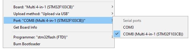
1. In the Arduino IDE click **Sketch -> Upload**, or press **Ctrl+U**
**Note:** If the module appears as a **Maple DFU** for a module with only a bootloader, **Maple Serial** for a module with a bootloader and firmware then follow the same process by selecting any available COM port (you must select one, if you don't have one appearing plug any device that will create a com port (an Arduino board for example)).
You should see output similar to this:
```
Sketch uses 68564 bytes (52%) of program storage space. Maximum is 131072 bytes.
Global variables use 4064 bytes (19%) of dynamic memory, leaving 16416 bytes for local variables. Maximum is 20480 bytes.
C:\Users\blye\AppData\Local\Arduino15\packages\multi4in1\hardware\STM32F1\1.0.0/tools/win/maple_upload.bat COM4 2 1EAF:0003 C:\Users\blye\AppData\Local\Temp\arduino_build_933551/Multiprotocol.ino.bin
maple_loader v0.1
Resetting to bootloader via DTR pulse
Reset via USB Serial Failed! Did you select the right serial port?
Searching for DFU device [1EAF:0003]...
Assuming the board is in perpetual bootloader mode and continuing to attempt dfu programming...
Found it!
Opening USB Device 0x1eaf:0x0003...
Found Runtime: [0x1eaf:0x0003] devnum=1, cfg=0, intf=0, alt=2, name="STM32duino bootloader v1.0 Upload to Flash 0x8002000"
Setting Configuration 1...
Claiming USB DFU Interface...
Setting Alternate Setting ...
Determining device status: state = dfuIDLE, status = 0
dfuIDLE, continuing
Transfer Size = 0x0400
bytes_per_hash=1371
Starting download: [##################################################] finished!
state(8) = dfuMANIFEST-WAIT-RESET, status(0) = No error condition is present
Done!
Resetting USB to switch back to runtime mode
error resetting after download: usb_reset: could not reset device, win error: The system cannot find the file specified.
```
**Note:** The line `Reset via USB Serial Failed! Did you select the right serial port?` or a warning line stating that the device could not be reset is **not a problem**.
## Troubleshooting
You can report your problem using the [GitHub issue](https://github.com/midelic/DIY-Multiprotocol-TX-Module/issues) system or go to the [Main thread on RCGROUPS](http://www.rcgroups.com/forums/showthread.php?t=2165676) to ask your question.
Please provide the following information:
- Multiprotocol code version
- STM32 version
- TX type
- Using PPM or Serial, if using er9x or ersky9x the version in use
- Different led status (multimodule and model)
- Explanation of the behavior and reproduction steps