mirror of
https://github.com/pascallanger/DIY-Multiprotocol-TX-Module.git
synced 2025-11-25 21:39:39 +00:00
Compare commits
46 Commits
| Author | SHA1 | Date | |
|---|---|---|---|
|
|
f912d84ab6 | ||
|
|
85548d6e8e | ||
|
|
c74de12ceb | ||
|
|
017a21c17f | ||
|
|
9a63038a5f | ||
|
|
304fc2536b | ||
|
|
365169a9fb | ||
|
|
4b82ead18b | ||
|
|
141d7cc268 | ||
|
|
ee8e94cfb0 | ||
|
|
b50bedef39 | ||
|
|
a689ce4de9 | ||
|
|
ae0478a7e9 | ||
|
|
ee6eed5ac5 | ||
|
|
9140c426c4 | ||
|
|
a41bfabede | ||
|
|
5d26357025 | ||
|
|
644c10e994 | ||
|
|
b3ca0beead | ||
|
|
93300c6821 | ||
|
|
2bd8d7ee32 | ||
|
|
95c339ef74 | ||
|
|
76ad1d5ef7 | ||
|
|
151e82a2c3 | ||
|
|
3fcaf93788 | ||
|
|
b8927d66e9 | ||
|
|
9273f364fc | ||
|
|
bc42dbf88a | ||
|
|
481d4c15d6 | ||
|
|
563030e732 | ||
|
|
4f9137d009 | ||
|
|
ed1b4d1885 | ||
|
|
6bbcd9020e | ||
|
|
0ba916a7d6 | ||
|
|
cf498462eb | ||
|
|
e8b8b861a4 | ||
|
|
4afb045234 | ||
|
|
ef5c876085 | ||
|
|
7fbcfeec9c | ||
|
|
2981a8ef83 | ||
|
|
b1e8bfe2ab | ||
|
|
623d568eb9 | ||
|
|
3625834be3 | ||
|
|
925a4f4a57 | ||
|
|
0729b21e67 | ||
|
|
393d37a8c6 |
@@ -140,19 +140,18 @@ void A7105_WriteID(uint32_t ida) {
|
||||
CS_on;
|
||||
}
|
||||
|
||||
void A7105_SetPower_Value(int power)
|
||||
/*
|
||||
static void A7105_SetPower_Value(int power)
|
||||
{
|
||||
/*
|
||||
Power amp is ~+16dBm so:
|
||||
TXPOWER_100uW = -23dBm == PAC=0 TBG=0
|
||||
TXPOWER_300uW = -20dBm == PAC=0 TBG=1
|
||||
TXPOWER_1mW = -16dBm == PAC=0 TBG=2
|
||||
TXPOWER_3mW = -11dBm == PAC=0 TBG=4
|
||||
TXPOWER_10mW = -6dBm == PAC=1 TBG=5
|
||||
TXPOWER_30mW = 0dBm == PAC=2 TBG=7
|
||||
TXPOWER_100mW = 1dBm == PAC=3 TBG=7
|
||||
TXPOWER_150mW = 1dBm == PAC=3 TBG=7
|
||||
*/
|
||||
//Power amp is ~+16dBm so:
|
||||
//TXPOWER_100uW = -23dBm == PAC=0 TBG=0
|
||||
//TXPOWER_300uW = -20dBm == PAC=0 TBG=1
|
||||
//TXPOWER_1mW = -16dBm == PAC=0 TBG=2
|
||||
//TXPOWER_3mW = -11dBm == PAC=0 TBG=4
|
||||
//TXPOWER_10mW = -6dBm == PAC=1 TBG=5
|
||||
//TXPOWER_30mW = 0dBm == PAC=2 TBG=7
|
||||
//TXPOWER_100mW = 1dBm == PAC=3 TBG=7
|
||||
//TXPOWER_150mW = 1dBm == PAC=3 TBG=7
|
||||
uint8_t pac, tbg;
|
||||
switch(power) {
|
||||
case 0: pac = 0; tbg = 0; break;
|
||||
@@ -167,6 +166,7 @@ void A7105_SetPower_Value(int power)
|
||||
};
|
||||
A7105_WriteReg(0x28, (pac << 3) | tbg);
|
||||
}
|
||||
*/
|
||||
|
||||
void A7105_SetPower()
|
||||
{
|
||||
@@ -196,6 +196,8 @@ const uint8_t PROGMEM FLYSKY_A7105_regs[] = {
|
||||
0x13, 0xc3, 0x00, 0xff, 0x00, 0x00, 0x3b, 0x00, 0x17, 0x47, 0x80, 0x03, 0x01, 0x45, 0x18, 0x00,
|
||||
0x01, 0x0f, 0xff
|
||||
};
|
||||
#define ID_NORMAL 0x55201041
|
||||
#define ID_PLUS 0xAA201041
|
||||
void A7105_Init(uint8_t protocol)
|
||||
{
|
||||
void *A7105_Regs;
|
||||
@@ -207,7 +209,7 @@ void A7105_Init(uint8_t protocol)
|
||||
}
|
||||
else
|
||||
{
|
||||
A7105_WriteID(0x55201041);
|
||||
A7105_WriteID(ID_NORMAL);
|
||||
A7105_Regs=(void *)HUBSAN_A7105_regs;
|
||||
}
|
||||
for (uint8_t i = 0; i < 0x33; i++){
|
||||
|
||||
@@ -4,7 +4,7 @@
|
||||
the Free Software Foundation, either version 3 of the License, or
|
||||
(at your option) any later version.
|
||||
|
||||
Multiprotocol is distributed in the hope that it will be useful,
|
||||
Multiprotocol is distributed in the hope that it will be useful,
|
||||
but WITHOUT ANY WARRANTY; without even the implied warranty of
|
||||
MERCHANTABILITY or FITNESS FOR A PARTICULAR PURPOSE. See the
|
||||
GNU General Public License for more details.
|
||||
@@ -12,7 +12,8 @@
|
||||
You should have received a copy of the GNU General Public License
|
||||
along with Multiprotocol. If not, see <http://www.gnu.org/licenses/>.
|
||||
*/
|
||||
// compatible with EAchine H8 mini, H10, BayangToys X6/X7/X9, JJRC JJ850 ...
|
||||
// Compatible with EAchine H8 mini, H10, BayangToys X6/X7/X9, JJRC JJ850 ...
|
||||
// Last sync with hexfet new_protocols/bayang_nrf24l01.c dated 2015-12-22
|
||||
|
||||
#if defined(BAYANG_NRF24L01_INO)
|
||||
|
||||
@@ -30,15 +31,14 @@ enum BAYANG_FLAGS {
|
||||
// flags going to packet[2]
|
||||
BAYANG_FLAG_RTH = 0x01,
|
||||
BAYANG_FLAG_HEADLESS = 0x02,
|
||||
BAYANG_FLAG_FLIP = 0x08
|
||||
BAYANG_FLAG_FLIP = 0x08,
|
||||
BAYANG_FLAG_VIDEO = 0x10,
|
||||
BAYANG_FLAG_PICTURE = 0x20,
|
||||
// flags going to packet[3]
|
||||
BAYANG_FLAG_INVERTED = 0x80 // inverted flight on Floureon H101
|
||||
};
|
||||
|
||||
enum BAYANG_PHASES {
|
||||
BAYANG_BIND = 0,
|
||||
BAYANG_DATA
|
||||
};
|
||||
|
||||
void BAYANG_send_packet(uint8_t bind)
|
||||
static void __attribute__((unused)) BAYANG_send_packet(uint8_t bind)
|
||||
{
|
||||
uint8_t i;
|
||||
if (bind)
|
||||
@@ -48,8 +48,8 @@ void BAYANG_send_packet(uint8_t bind)
|
||||
packet[i+1]=rx_tx_addr[i];
|
||||
for(i=0;i<4;i++)
|
||||
packet[i+6]=hopping_frequency[i];
|
||||
packet[10] = rx_tx_addr[0];
|
||||
packet[11] = rx_tx_addr[1];
|
||||
packet[10] = rx_tx_addr[0]; // txid[0]
|
||||
packet[11] = rx_tx_addr[1]; // txid[1]
|
||||
}
|
||||
else
|
||||
{
|
||||
@@ -57,16 +57,22 @@ void BAYANG_send_packet(uint8_t bind)
|
||||
packet[0] = 0xA5;
|
||||
packet[1] = 0xFA; // normal mode is 0xf7, expert 0xfa
|
||||
|
||||
//Flags
|
||||
packet[2] =0x00;
|
||||
if(Servo_data[AUX1] > PPM_SWITCH)
|
||||
packet[2] |= BAYANG_FLAG_FLIP;
|
||||
if(Servo_data[AUX2] > PPM_SWITCH)
|
||||
packet[2] |= BAYANG_FLAG_HEADLESS;
|
||||
if(Servo_data[AUX3] > PPM_SWITCH)
|
||||
//Flags packet[2]
|
||||
packet[2] = 0x00;
|
||||
if(Servo_AUX1)
|
||||
packet[2] = BAYANG_FLAG_FLIP;
|
||||
if(Servo_AUX2)
|
||||
packet[2] |= BAYANG_FLAG_RTH;
|
||||
|
||||
if(Servo_AUX3)
|
||||
packet[2] |= BAYANG_FLAG_PICTURE;
|
||||
if(Servo_AUX4)
|
||||
packet[2] |= BAYANG_FLAG_VIDEO;
|
||||
if(Servo_AUX5)
|
||||
packet[2] |= BAYANG_FLAG_HEADLESS;
|
||||
//Flags packet[3]
|
||||
packet[3] = 0x00;
|
||||
if(Servo_AUX6)
|
||||
packet[3] = BAYANG_FLAG_INVERTED;
|
||||
|
||||
//Aileron
|
||||
val = convert_channel_10b(AILERON);
|
||||
@@ -85,7 +91,7 @@ void BAYANG_send_packet(uint8_t bind)
|
||||
packet[10] = (val>>8) + (val>>2 & 0xFC);
|
||||
packet[11] = val & 0xFF;
|
||||
}
|
||||
packet[12] = rx_tx_addr[2];
|
||||
packet[12] = rx_tx_addr[2]; // txid[2]
|
||||
packet[13] = 0x0A;
|
||||
packet[14] = 0;
|
||||
for (uint8_t i=0; i < BAYANG_PACKET_SIZE-1; i++)
|
||||
@@ -95,10 +101,7 @@ void BAYANG_send_packet(uint8_t bind)
|
||||
// Why CRC0? xn297 does not interpret it - either 16-bit CRC or nothing
|
||||
XN297_Configure(BV(NRF24L01_00_EN_CRC) | BV(NRF24L01_00_CRCO) | BV(NRF24L01_00_PWR_UP));
|
||||
|
||||
if (bind)
|
||||
NRF24L01_WriteReg(NRF24L01_05_RF_CH, BAYANG_RF_BIND_CHANNEL);
|
||||
else
|
||||
NRF24L01_WriteReg(NRF24L01_05_RF_CH, hopping_frequency[hopping_frequency_no++]);
|
||||
NRF24L01_WriteReg(NRF24L01_05_RF_CH, bind ? BAYANG_RF_BIND_CHANNEL:hopping_frequency[hopping_frequency_no++]);
|
||||
hopping_frequency_no%=BAYANG_RF_NUM_CHANNELS;
|
||||
|
||||
// clear packet status bits and TX FIFO
|
||||
@@ -109,7 +112,7 @@ void BAYANG_send_packet(uint8_t bind)
|
||||
NRF24L01_SetPower(); // Set tx_power
|
||||
}
|
||||
|
||||
void BAYANG_init()
|
||||
static void __attribute__((unused)) BAYANG_init()
|
||||
{
|
||||
NRF24L01_Initialize();
|
||||
NRF24L01_SetTxRxMode(TX_EN);
|
||||
@@ -118,49 +121,40 @@ void BAYANG_init()
|
||||
|
||||
NRF24L01_FlushTx();
|
||||
NRF24L01_FlushRx();
|
||||
NRF24L01_WriteReg(NRF24L01_07_STATUS, 0x70); // Clear data ready, data sent, and retransmit
|
||||
NRF24L01_WriteReg(NRF24L01_01_EN_AA, 0x00); // No Auto Acknowldgement on all data pipes
|
||||
NRF24L01_WriteReg(NRF24L01_02_EN_RXADDR, 0x01); // Enable data pipe 0 only
|
||||
NRF24L01_WriteReg(NRF24L01_03_SETUP_AW, 0x03);
|
||||
NRF24L01_WriteReg(NRF24L01_04_SETUP_RETR, 0x00); // no retransmits
|
||||
NRF24L01_SetBitrate(NRF24L01_BR_1M); // 1Mbps
|
||||
NRF24L01_SetPower();
|
||||
|
||||
NRF24L01_Activate(0x73); // Activate feature register
|
||||
NRF24L01_WriteReg(NRF24L01_1C_DYNPD, 0x00); // Disable dynamic payload length on all pipes
|
||||
NRF24L01_WriteReg(NRF24L01_1D_FEATURE, 0x01);
|
||||
NRF24L01_Activate(0x73);
|
||||
NRF24L01_WriteReg(NRF24L01_02_EN_RXADDR, 0x01); // Enable data pipe 0 only
|
||||
NRF24L01_SetBitrate(NRF24L01_BR_1M); // 1Mbps
|
||||
NRF24L01_SetPower();
|
||||
}
|
||||
|
||||
uint16_t BAYANG_callback()
|
||||
{
|
||||
switch (phase)
|
||||
if(IS_BIND_DONE_on)
|
||||
BAYANG_send_packet(0);
|
||||
else
|
||||
{
|
||||
case BAYANG_BIND:
|
||||
if (bind_counter == 0)
|
||||
{
|
||||
XN297_SetTXAddr(rx_tx_addr, BAYANG_ADDRESS_LENGTH);
|
||||
phase = BAYANG_DATA;
|
||||
BIND_DONE;
|
||||
}
|
||||
else
|
||||
{
|
||||
BAYANG_send_packet(1);
|
||||
bind_counter--;
|
||||
}
|
||||
break;
|
||||
case BAYANG_DATA:
|
||||
BAYANG_send_packet(0);
|
||||
break;
|
||||
if (bind_counter == 0)
|
||||
{
|
||||
XN297_SetTXAddr(rx_tx_addr, BAYANG_ADDRESS_LENGTH);
|
||||
BIND_DONE;
|
||||
}
|
||||
else
|
||||
{
|
||||
BAYANG_send_packet(1);
|
||||
bind_counter--;
|
||||
}
|
||||
}
|
||||
return BAYANG_PACKET_PERIOD;
|
||||
}
|
||||
|
||||
void BAYANG_initialize_txid()
|
||||
static void __attribute__((unused)) BAYANG_initialize_txid()
|
||||
{
|
||||
// Strange txid, rx_tx_addr and rf_channels could be anything so I will use on rx_tx_addr for all of them...
|
||||
// Strange also that there is no check of duplicated rf channels... I think we need to implement that later...
|
||||
for(uint8_t i=0; i<BAYANG_RF_NUM_CHANNELS; i++)
|
||||
hopping_frequency[i]=rx_tx_addr[i]%42;
|
||||
//Could be using txid[0..2] but using rx_tx_addr everywhere instead...
|
||||
hopping_frequency[0]=0;
|
||||
hopping_frequency[1]=(rx_tx_addr[0]&0x1F)+0x10;
|
||||
hopping_frequency[2]=hopping_frequency[1]+0x20;
|
||||
hopping_frequency[3]=hopping_frequency[2]+0x20;
|
||||
hopping_frequency_no=0;
|
||||
}
|
||||
|
||||
@@ -169,9 +163,8 @@ uint16_t initBAYANG(void)
|
||||
BIND_IN_PROGRESS; // autobind protocol
|
||||
bind_counter = BAYANG_BIND_COUNT;
|
||||
BAYANG_initialize_txid();
|
||||
phase=BAYANG_BIND;
|
||||
BAYANG_init();
|
||||
return BAYANG_INITIAL_WAIT+BAYANG_PACKET_PERIOD;
|
||||
}
|
||||
|
||||
#endif
|
||||
#endif
|
||||
@@ -36,7 +36,7 @@ static void ReadRegisterMulti(uint8_t address, uint8_t data[], uint8_t length)
|
||||
|
||||
//*********************************************
|
||||
|
||||
void CC2500_WriteRegisterMulti(uint8_t address, const uint8_t data[], uint8_t length)
|
||||
static void CC2500_WriteRegisterMulti(uint8_t address, const uint8_t data[], uint8_t length)
|
||||
{
|
||||
CC25_CSN_off;
|
||||
cc2500_spi_write(CC2500_WRITE_BURST | address);
|
||||
@@ -53,7 +53,7 @@ void cc2500_writeFifo(uint8_t *dpbuffer, uint8_t len)
|
||||
}
|
||||
|
||||
//--------------------------------------
|
||||
void cc2500_spi_write(uint8_t command) {
|
||||
static void cc2500_spi_write(uint8_t command) {
|
||||
uint8_t n=8;
|
||||
|
||||
SCK_off;//SCK start low
|
||||
@@ -81,7 +81,7 @@ void cc2500_writeReg(uint8_t address, uint8_t data) {//same as 7105
|
||||
CC25_CSN_on;
|
||||
}
|
||||
|
||||
uint8_t cc2500_spi_read(void)
|
||||
static uint8_t cc2500_spi_read(void)
|
||||
{
|
||||
uint8_t result;
|
||||
uint8_t i;
|
||||
@@ -101,7 +101,7 @@ uint8_t cc2500_spi_read(void)
|
||||
}
|
||||
|
||||
//--------------------------------------------
|
||||
uint8_t cc2500_readReg(uint8_t address)
|
||||
static uint8_t cc2500_readReg(uint8_t address)
|
||||
{
|
||||
uint8_t result;
|
||||
CC25_CSN_off;
|
||||
@@ -119,7 +119,7 @@ void cc2500_strobe(uint8_t address)
|
||||
CC25_CSN_on;
|
||||
}
|
||||
//------------------------
|
||||
void cc2500_resetChip(void)
|
||||
/*static void cc2500_resetChip(void)
|
||||
{
|
||||
// Toggle chip select signal
|
||||
CC25_CSN_on;
|
||||
@@ -131,7 +131,7 @@ void cc2500_resetChip(void)
|
||||
cc2500_strobe(CC2500_SRES);
|
||||
_delay_ms(100);
|
||||
}
|
||||
|
||||
*/
|
||||
uint8_t CC2500_Reset()
|
||||
{
|
||||
cc2500_strobe(CC2500_SRES);
|
||||
@@ -139,8 +139,8 @@ uint8_t CC2500_Reset()
|
||||
CC2500_SetTxRxMode(TXRX_OFF);
|
||||
return cc2500_readReg(CC2500_0E_FREQ1) == 0xC4;//check if reset
|
||||
}
|
||||
|
||||
void CC2500_SetPower_Value(uint8_t power)
|
||||
/*
|
||||
static void CC2500_SetPower_Value(uint8_t power)
|
||||
{
|
||||
const unsigned char patable[8]= {
|
||||
0xC5, // -12dbm
|
||||
@@ -156,7 +156,7 @@ void CC2500_SetPower_Value(uint8_t power)
|
||||
power = 7;
|
||||
cc2500_writeReg(CC2500_3E_PATABLE, patable[power]);
|
||||
}
|
||||
|
||||
*/
|
||||
void CC2500_SetPower()
|
||||
{
|
||||
uint8_t power=CC2500_BIND_POWER;
|
||||
|
||||
@@ -12,7 +12,10 @@
|
||||
You should have received a copy of the GNU General Public License
|
||||
along with Multiprotocol. If not, see <http://www.gnu.org/licenses/>.
|
||||
*/
|
||||
// compatible with EAchine 3D X4, CG023/CG031, Attop YD-822/YD-829/YD-829C
|
||||
// compatible with EAchine 3D X4, CG023/CG031, Attop YD-822/YD-829/YD-829C and H8_3D/JJRC H20/H22
|
||||
// Merged CG023 and H8_3D protocols
|
||||
// Last sync with hexfet new_protocols/cg023_nrf24l01.c dated 2015-10-03
|
||||
// Last sync with hexfet new_protocols/h8_3d_nrf24l01.c dated 2015-11-18
|
||||
|
||||
#if defined(CG023_NRF24L01_INO)
|
||||
|
||||
@@ -22,8 +25,12 @@
|
||||
#define CG023_INITIAL_WAIT 500
|
||||
#define CG023_PACKET_SIZE 15 // packets have 15-byte payload
|
||||
#define CG023_RF_BIND_CHANNEL 0x2D
|
||||
#define CG023_BIND_COUNT 800 // 6 seconds
|
||||
#define CG023_BIND_COUNT 1000 // 8 seconds
|
||||
#define YD829_PACKET_PERIOD 4100 // Timeout for callback in uSec
|
||||
#define H8_3D_PACKET_PERIOD 1800 // Timeout for callback in uSec
|
||||
#define H8_3D_PACKET_SIZE 20
|
||||
#define H8_3D_RF_NUM_CHANNELS 4
|
||||
|
||||
|
||||
enum CG023_FLAGS {
|
||||
// flags going to packet[13]
|
||||
@@ -48,91 +55,164 @@ enum YD829_FLAGS {
|
||||
YD829_FLAG_STILL = 0x80,
|
||||
};
|
||||
|
||||
enum CG023_PHASES {
|
||||
CG023_BIND = 0,
|
||||
CG023_DATA
|
||||
enum H8_3D_FLAGS {
|
||||
// flags going to packet[17]
|
||||
H8_3D_FLAG_FLIP = 0x01,
|
||||
H8_3D_FLAG_RATE_MID = 0x02,
|
||||
H8_3D_FLAG_RATE_HIGH = 0x04,
|
||||
H8_3D_FLAG_LIGTH = 0x08, // Light on H22
|
||||
H8_3D_FLAG_HEADLESS = 0x10, // RTH + headless on H8, headless on JJRC H20, RTH on H22
|
||||
H8_3D_FLAG_RTH = 0x20, // 360 flip mode on H8 3D and H22, RTH on JJRC H20
|
||||
};
|
||||
|
||||
void CG023_send_packet(uint8_t bind)
|
||||
enum H8_3D_FLAGS_2 {
|
||||
// flags going to packet[18]
|
||||
H8_3D_FLAG_CALIBRATE = 0x20, // accelerometer calibration
|
||||
};
|
||||
|
||||
static void __attribute__((unused)) CG023_send_packet(uint8_t bind)
|
||||
{
|
||||
if (bind)
|
||||
packet[0]= 0xaa;
|
||||
else
|
||||
packet[0]= 0x55;
|
||||
// transmitter id
|
||||
// throttle : 0x00 - 0xFF
|
||||
throttle=convert_channel_8b(THROTTLE);
|
||||
// rudder
|
||||
rudder = convert_channel_8b_scale(RUDDER,0x44,0xBC); // yaw right : 0x80 (neutral) - 0xBC (right)
|
||||
if (rudder<=0x80)
|
||||
rudder=0x80-rudder; // yaw left : 0x00 (neutral) - 0x3C (left)
|
||||
// elevator : 0xBB - 0x7F - 0x43
|
||||
elevator = convert_channel_8b_scale(ELEVATOR, 0x43, 0xBB);
|
||||
// aileron : 0x43 - 0x7F - 0xBB
|
||||
aileron = convert_channel_8b_scale(AILERON, 0x43, 0xBB);
|
||||
|
||||
packet[1] = rx_tx_addr[0];
|
||||
packet[2] = rx_tx_addr[1];
|
||||
// unknown
|
||||
packet[3] = 0x00;
|
||||
packet[4] = 0x00;
|
||||
// throttle : 0x00 - 0xFF
|
||||
packet[5] = convert_channel_8b(THROTTLE);
|
||||
// rudder
|
||||
packet[6] = convert_channel_8b_scale(RUDDER,0x44,0xBC); // yaw right : 0x80 (neutral) - 0xBC (right)
|
||||
if (packet[6]<=0x80)
|
||||
packet[6]=0x80-packet[6]; // yaw left : 0x00 (neutral) - 0x3C (left)
|
||||
// elevator : 0xBB - 0x7F - 0x43
|
||||
packet[7] = convert_channel_8b_scale(ELEVATOR, 0x43, 0xBB);
|
||||
// aileron : 0x43 - 0x7F - 0xBB
|
||||
packet[8] = convert_channel_8b_scale(AILERON, 0x43, 0xBB);
|
||||
// throttle trim : 0x30 - 0x20 - 0x10
|
||||
packet[9] = 0x20; // neutral
|
||||
// neutral trims
|
||||
packet[10] = 0x20;
|
||||
packet[11] = 0x40;
|
||||
packet[12] = 0x40;
|
||||
if(sub_protocol==CG023)
|
||||
if(sub_protocol==H8_3D)
|
||||
{
|
||||
// rate
|
||||
packet[13] = CG023_FLAG_RATE_HIGH;
|
||||
// flags
|
||||
if(Servo_data[AUX1] > PPM_SWITCH)
|
||||
packet[13] |= CG023_FLAG_FLIP;
|
||||
if(Servo_data[AUX2] > PPM_SWITCH)
|
||||
packet[13] |= CG023_FLAG_LED_OFF;
|
||||
if(Servo_data[AUX3] > PPM_SWITCH)
|
||||
packet[13] |= CG023_FLAG_STILL;
|
||||
if(Servo_data[AUX4] > PPM_SWITCH)
|
||||
packet[13] |= CG023_FLAG_VIDEO;
|
||||
if(Servo_data[AUX5] > PPM_SWITCH)
|
||||
packet[13] |= CG023_FLAG_EASY;
|
||||
packet[0] = 0x13;
|
||||
packet[3] = rx_tx_addr[2];
|
||||
packet[4] = rx_tx_addr[3];
|
||||
packet[8] = rx_tx_addr[0]+rx_tx_addr[1]+rx_tx_addr[2]+rx_tx_addr[3]; // txid checksum
|
||||
memset(&packet[9], 0, 10);
|
||||
if (bind)
|
||||
{
|
||||
packet[5] = 0x00;
|
||||
packet[6] = 0x00;
|
||||
packet[7] = 0x01;
|
||||
}
|
||||
else
|
||||
{
|
||||
packet[5] = hopping_frequency_no;
|
||||
packet[6] = 0x08;
|
||||
packet[7] = 0x03;
|
||||
packet[9] = throttle;
|
||||
packet[10] = rudder;
|
||||
packet[11] = elevator;
|
||||
packet[12] = aileron;
|
||||
// neutral trims
|
||||
packet[13] = 0x20;
|
||||
packet[14] = 0x20;
|
||||
packet[15] = 0x20;
|
||||
packet[16] = 0x20;
|
||||
packet[17] = H8_3D_FLAG_RATE_HIGH;
|
||||
if(Servo_AUX1)
|
||||
packet[17] |= H8_3D_FLAG_FLIP;
|
||||
if(Servo_AUX2)
|
||||
packet[17] |= H8_3D_FLAG_LIGTH; //H22 light
|
||||
if(Servo_AUX3)
|
||||
packet[17] |= H8_3D_FLAG_HEADLESS;
|
||||
if(Servo_AUX4)
|
||||
packet[17] |= H8_3D_FLAG_RTH; // 180/360 flip mode on H8 3D
|
||||
if(Servo_AUX5)
|
||||
packet[18] = H8_3D_FLAG_CALIBRATE;
|
||||
}
|
||||
uint8_t sum = packet[9];
|
||||
for (uint8_t i=10; i < H8_3D_PACKET_SIZE-1; i++)
|
||||
sum += packet[i];
|
||||
packet[19] = sum; // data checksum
|
||||
}
|
||||
else
|
||||
{// YD829
|
||||
// rate
|
||||
packet[13] = YD829_FLAG_RATE_HIGH;
|
||||
// flags
|
||||
if(Servo_data[AUX1] > PPM_SWITCH)
|
||||
packet[13] |= YD829_FLAG_FLIP;
|
||||
if(Servo_data[AUX3] > PPM_SWITCH)
|
||||
packet[13] |= YD829_FLAG_STILL;
|
||||
if(Servo_data[AUX4] > PPM_SWITCH)
|
||||
packet[13] |= YD829_FLAG_VIDEO;
|
||||
if(Servo_data[AUX5] > PPM_SWITCH)
|
||||
packet[13] |= YD829_FLAG_HEADLESS;
|
||||
{ // CG023 and YD829
|
||||
if (bind)
|
||||
packet[0]= 0xaa;
|
||||
else
|
||||
packet[0]= 0x55;
|
||||
// transmitter id
|
||||
// unknown
|
||||
packet[3] = 0x00;
|
||||
packet[4] = 0x00;
|
||||
packet[5] = throttle;
|
||||
packet[6] = rudder;
|
||||
packet[7] = elevator;
|
||||
packet[8] = aileron;
|
||||
// throttle trim : 0x30 - 0x20 - 0x10
|
||||
packet[9] = 0x20; // neutral
|
||||
// neutral trims
|
||||
packet[10] = 0x20;
|
||||
packet[11] = 0x40;
|
||||
packet[12] = 0x40;
|
||||
if(sub_protocol==CG023)
|
||||
{
|
||||
// rate
|
||||
packet[13] = CG023_FLAG_RATE_HIGH;
|
||||
// flags
|
||||
if(Servo_AUX1)
|
||||
packet[13] |= CG023_FLAG_FLIP;
|
||||
if(Servo_AUX2)
|
||||
packet[13] |= CG023_FLAG_LED_OFF;
|
||||
if(Servo_AUX3)
|
||||
packet[13] |= CG023_FLAG_STILL;
|
||||
if(Servo_AUX4)
|
||||
packet[13] |= CG023_FLAG_VIDEO;
|
||||
if(Servo_AUX5)
|
||||
packet[13] |= CG023_FLAG_EASY;
|
||||
}
|
||||
else
|
||||
{// YD829
|
||||
// rate
|
||||
packet[13] = YD829_FLAG_RATE_HIGH;
|
||||
// flags
|
||||
if(Servo_AUX1)
|
||||
packet[13] |= YD829_FLAG_FLIP;
|
||||
if(Servo_AUX3)
|
||||
packet[13] |= YD829_FLAG_STILL;
|
||||
if(Servo_AUX4)
|
||||
packet[13] |= YD829_FLAG_VIDEO;
|
||||
if(Servo_AUX5)
|
||||
packet[13] |= YD829_FLAG_HEADLESS;
|
||||
}
|
||||
packet[14] = 0;
|
||||
}
|
||||
packet[14] = 0;
|
||||
|
||||
|
||||
// Power on, TX mode, 2byte CRC
|
||||
// Why CRC0? xn297 does not interpret it - either 16-bit CRC or nothing
|
||||
XN297_Configure(BV(NRF24L01_00_EN_CRC) | BV(NRF24L01_00_CRCO) | BV(NRF24L01_00_PWR_UP));
|
||||
if (bind)
|
||||
NRF24L01_WriteReg(NRF24L01_05_RF_CH, CG023_RF_BIND_CHANNEL);
|
||||
NRF24L01_WriteReg(NRF24L01_05_RF_CH, sub_protocol==H8_3D?hopping_frequency[0]:CG023_RF_BIND_CHANNEL);
|
||||
else
|
||||
NRF24L01_WriteReg(NRF24L01_05_RF_CH, hopping_frequency_no);
|
||||
{
|
||||
if(sub_protocol==H8_3D)
|
||||
{
|
||||
NRF24L01_WriteReg(NRF24L01_05_RF_CH, hopping_frequency[hopping_frequency_no++]);
|
||||
hopping_frequency_no %= H8_3D_RF_NUM_CHANNELS;
|
||||
}
|
||||
else // CG023 and YD829
|
||||
NRF24L01_WriteReg(NRF24L01_05_RF_CH, hopping_frequency_no);
|
||||
}
|
||||
// clear packet status bits and TX FIFO
|
||||
NRF24L01_WriteReg(NRF24L01_07_STATUS, 0x70);
|
||||
NRF24L01_FlushTx();
|
||||
XN297_WritePayload(packet, CG023_PACKET_SIZE);
|
||||
XN297_WritePayload(packet, sub_protocol==H8_3D ? H8_3D_PACKET_SIZE:CG023_PACKET_SIZE);
|
||||
|
||||
NRF24L01_SetPower(); // Set tx_power
|
||||
}
|
||||
|
||||
void CG023_init()
|
||||
static void __attribute__((unused)) CG023_init()
|
||||
{
|
||||
NRF24L01_Initialize();
|
||||
NRF24L01_SetTxRxMode(TX_EN);
|
||||
XN297_SetTXAddr((uint8_t *)"\x26\xA8\x67\x35\xCC", 5);
|
||||
if(sub_protocol==H8_3D)
|
||||
XN297_SetTXAddr((uint8_t *)"\xC4\x57\x09\x65\x21", 5);
|
||||
else // CG023 and YD829
|
||||
XN297_SetTXAddr((uint8_t *)"\x26\xA8\x67\x35\xCC", 5);
|
||||
|
||||
NRF24L01_FlushTx();
|
||||
NRF24L01_FlushRx();
|
||||
@@ -145,37 +225,48 @@ void CG023_init()
|
||||
|
||||
uint16_t CG023_callback()
|
||||
{
|
||||
switch (phase)
|
||||
if(IS_BIND_DONE_on)
|
||||
CG023_send_packet(0);
|
||||
else
|
||||
{
|
||||
case CG023_BIND:
|
||||
if (bind_counter == 0)
|
||||
{
|
||||
phase = CG023_DATA;
|
||||
BIND_DONE;
|
||||
}
|
||||
else
|
||||
{
|
||||
CG023_send_packet(1);
|
||||
bind_counter--;
|
||||
}
|
||||
break;
|
||||
case CG023_DATA:
|
||||
CG023_send_packet(0);
|
||||
break;
|
||||
if (bind_counter == 0)
|
||||
BIND_DONE;
|
||||
else
|
||||
{
|
||||
CG023_send_packet(1);
|
||||
bind_counter--;
|
||||
}
|
||||
}
|
||||
|
||||
if(sub_protocol==CG023)
|
||||
return CG023_PACKET_PERIOD;
|
||||
else
|
||||
return YD829_PACKET_PERIOD;
|
||||
if(sub_protocol==YD829)
|
||||
return YD829_PACKET_PERIOD;
|
||||
return H8_3D_PACKET_PERIOD;
|
||||
}
|
||||
|
||||
void CG023_initialize_txid()
|
||||
static void __attribute__((unused)) CG023_initialize_txid()
|
||||
{
|
||||
rx_tx_addr[0]= 0x80 | (rx_tx_addr[0] % 0x40);
|
||||
if( rx_tx_addr[0] == 0xAA) // avoid using same freq for bind and data channel
|
||||
rx_tx_addr[0] ++;
|
||||
|
||||
hopping_frequency_no = rx_tx_addr[0] - 0x7D; // rf channel for data packets
|
||||
if(sub_protocol==H8_3D)
|
||||
{
|
||||
rx_tx_addr[0] = 0xa0 + (rx_tx_addr[0] % 0x10);
|
||||
rx_tx_addr[1] = 0xb0 + (rx_tx_addr[1] % 0x20);
|
||||
rx_tx_addr[2] = rx_tx_addr[2] % 0x20;
|
||||
rx_tx_addr[3] = rx_tx_addr[3] % 0x11;
|
||||
|
||||
hopping_frequency[0] = 0x06 + ((rx_tx_addr[0]&0x0f) % 0x0f);
|
||||
hopping_frequency[1] = 0x15 + ((rx_tx_addr[1]&0x0f) % 0x0f);
|
||||
hopping_frequency[2] = 0x24 + ((rx_tx_addr[2]&0x0f) % 0x0f);
|
||||
hopping_frequency[3] = 0x33 + ((rx_tx_addr[3]&0x0f) % 0x0f);
|
||||
}
|
||||
else
|
||||
{ // CG023 and YD829
|
||||
rx_tx_addr[0]= 0x80 | (rx_tx_addr[0] % 0x40);
|
||||
if( rx_tx_addr[0] == 0xAA) // avoid using same freq for bind and data channel
|
||||
rx_tx_addr[0] ++;
|
||||
hopping_frequency_no = rx_tx_addr[0] - 0x7D; // rf channel for data packets
|
||||
}
|
||||
}
|
||||
|
||||
uint16_t initCG023(void)
|
||||
@@ -184,11 +275,12 @@ uint16_t initCG023(void)
|
||||
bind_counter = CG023_BIND_COUNT;
|
||||
CG023_initialize_txid();
|
||||
CG023_init();
|
||||
phase=CG023_BIND;
|
||||
if(sub_protocol==CG023)
|
||||
return CG023_INITIAL_WAIT+CG023_PACKET_PERIOD;
|
||||
else
|
||||
return CG023_INITIAL_WAIT+YD829_PACKET_PERIOD;
|
||||
if(sub_protocol==YD829)
|
||||
return CG023_INITIAL_WAIT+YD829_PACKET_PERIOD;
|
||||
return CG023_INITIAL_WAIT+H8_3D_PACKET_PERIOD;
|
||||
}
|
||||
|
||||
#endif
|
||||
|
||||
@@ -13,6 +13,7 @@
|
||||
along with Multiprotocol. If not, see <http://www.gnu.org/licenses/>.
|
||||
*/
|
||||
// compatible with Cheerson CX-10 blue & newer red pcb, CX-10A, CX11, CX-10 green pcb, DM007, Floureon FX-10, CX-Stars
|
||||
// Last sync with hexfet new_protocols/cx10_nrf24l01.c dated 2015-11-26
|
||||
|
||||
#if defined(CX10_NRF24L01_INO)
|
||||
|
||||
@@ -21,6 +22,7 @@
|
||||
#define CX10_BIND_COUNT 4360 // 6 seconds
|
||||
#define CX10_PACKET_SIZE 15
|
||||
#define CX10A_PACKET_SIZE 19 // CX10 blue board packets have 19-byte payload
|
||||
#define Q282_PACKET_SIZE 21
|
||||
#define CX10_PACKET_PERIOD 1316 // Timeout for callback in uSec
|
||||
#define CX10A_PACKET_PERIOD 6000
|
||||
|
||||
@@ -39,13 +41,12 @@
|
||||
#define NUM_RF_CHANNELS 4
|
||||
|
||||
enum {
|
||||
CX10_INIT1 = 0,
|
||||
CX10_BIND1,
|
||||
CX10_BIND1 = 0,
|
||||
CX10_BIND2,
|
||||
CX10_DATA
|
||||
};
|
||||
|
||||
void CX10_Write_Packet(uint8_t bind)
|
||||
static void __attribute__((unused)) CX10_Write_Packet(uint8_t bind)
|
||||
{
|
||||
uint8_t offset = 0;
|
||||
if(sub_protocol == CX10_BLUE)
|
||||
@@ -66,32 +67,86 @@ void CX10_Write_Packet(uint8_t bind)
|
||||
packet[12+offset]= highByte(Servo_data[RUDDER]);
|
||||
|
||||
// Channel 5 - flip flag
|
||||
if(Servo_data[AUX1] > PPM_SWITCH)
|
||||
if(Servo_AUX1)
|
||||
packet[12+offset] |= CX10_FLAG_FLIP; // flip flag
|
||||
|
||||
// Channel 6 - mode
|
||||
if(Servo_data[AUX2] > PPM_MAX_COMMAND) // mode 3 / headless on CX-10A
|
||||
packet[13+offset] = 0x02;
|
||||
//flags=0; // packet 13
|
||||
uint8_t flags2=0; // packet 14
|
||||
|
||||
// Channel 6 - rate mode is 2 lsb of packet 13
|
||||
if(Servo_data[AUX2] > PPM_MAX_COMMAND) // rate 3 / headless on CX-10A
|
||||
flags = 0x02;
|
||||
else
|
||||
if(Servo_data[AUX2] < PPM_MIN_COMMAND)
|
||||
packet[13+offset] = 0x00; // mode 1
|
||||
flags = 0x00; // rate 1
|
||||
else
|
||||
packet[13+offset] = 0x01; // mode 2
|
||||
flags = 0x01; // rate 2
|
||||
|
||||
flags=0;
|
||||
if(sub_protocol == DM007)
|
||||
uint8_t video_state=packet[14] & 0x21;
|
||||
switch(sub_protocol)
|
||||
{
|
||||
// Channel 7 - snapshot
|
||||
if(Servo_data[AUX3] > PPM_SWITCH)
|
||||
flags |= CX10_FLAG_SNAPSHOT;
|
||||
// Channel 8 - video
|
||||
if(Servo_data[AUX4] > PPM_SWITCH)
|
||||
flags |= CX10_FLAG_VIDEO;
|
||||
// Channel 9 - headless
|
||||
if(Servo_data[AUX5] > PPM_SWITCH)
|
||||
packet[13+offset] |= CX10_FLAG_HEADLESS;
|
||||
case CX10_BLUE:
|
||||
if(Servo_AUX3) flags |= 0x10; // Channel 7 - picture
|
||||
if(Servo_AUX4) flags |= 0x08; // Channel 8 - video
|
||||
break;
|
||||
case Q282:
|
||||
case Q242:
|
||||
memcpy(&packet[15], "\x10\x10\xaa\xaa\x00\x00", 6);
|
||||
//FLIP|LED|PICTURE|VIDEO|HEADLESS|RTH|XCAL|YCAL
|
||||
if(Servo_AUX1) flags2 =0x80; // Channel 5 - FLIP
|
||||
if(Servo_AUX2) flags2|=0x40; // Channel 6 - LED
|
||||
|
||||
if(Servo_AUX5) flags2|=0x08; // Channel 9 - HEADLESS
|
||||
if(sub_protocol==Q282)
|
||||
{
|
||||
if(Servo_AUX3) flags2|=0x10; // Channel 7 - picture
|
||||
if(Servo_AUX4) // Channel 8 - video
|
||||
{
|
||||
if (!(video_state & 0x20)) video_state ^= 0x21;
|
||||
}
|
||||
else
|
||||
if (video_state & 0x20) video_state &= 0x01;
|
||||
flags2 |= video_state;
|
||||
flags=3;
|
||||
}
|
||||
else
|
||||
{
|
||||
if(Servo_AUX3) flags2|=0x01; // Channel 7 - picture
|
||||
if(Servo_AUX4) flags2|=0x10; // Channel 8 - video
|
||||
flags=2;
|
||||
packet[17]=0x00;
|
||||
packet[18]=0x00;
|
||||
}
|
||||
if(Servo_AUX6) flags |=0x80; // Channel 10 - RTH
|
||||
if(Servo_AUX7) flags2|=0x04; // Channel 11 - XCAL
|
||||
if(Servo_AUX8) flags2|=0x02; // Channel 12 - YCAL
|
||||
break;
|
||||
case DM007:
|
||||
//FLIP|MODE|PICTURE|VIDEO|HEADLESS
|
||||
if(Servo_AUX3) flags2 = CX10_FLAG_SNAPSHOT; // Channel 7 - picture
|
||||
if(Servo_AUX4) flags2|= CX10_FLAG_VIDEO; // Channel 8 - video
|
||||
if(Servo_AUX5) flags |= CX10_FLAG_HEADLESS; // Channel 9 - headless
|
||||
break;
|
||||
case JC3015_1:
|
||||
//FLIP|MODE|PICTURE|VIDEO
|
||||
if(Servo_AUX3) flags2 = _BV(3); // Channel 7 - picture
|
||||
if(Servo_AUX4) flags2|= _BV(4); // Channel 8 - video
|
||||
break;
|
||||
case JC3015_2:
|
||||
//FLIP|MODE|LED|DFLIP
|
||||
if(Servo_AUX3) flags2 = _BV(3); // Channel 7 - LED
|
||||
if(Servo_AUX4) flags2|= _BV(4); // Channel 8 - DFLIP
|
||||
break;
|
||||
case MK33041:
|
||||
//FLIP|MODE|PICTURE|VIDEO|HEADLESS|RTH
|
||||
if(Servo_AUX3) flags |= _BV(7); // Channel 7 - picture
|
||||
if(Servo_AUX4) flags2 = _BV(0); // Channel 8 - video
|
||||
if(Servo_AUX5) flags2|= _BV(5); // Channel 9 - headless
|
||||
if(Servo_AUX6) flags |= _BV(2); // Channel 10 - rth
|
||||
break;
|
||||
}
|
||||
packet[14+offset] = flags;
|
||||
packet[13+offset]=flags;
|
||||
packet[14+offset]=flags2;
|
||||
|
||||
// Power on, TX mode, 2byte CRC
|
||||
// Why CRC0? xn297 does not interpret it - either 16-bit CRC or nothing
|
||||
@@ -111,7 +166,7 @@ void CX10_Write_Packet(uint8_t bind)
|
||||
NRF24L01_SetPower();
|
||||
}
|
||||
|
||||
void CX10_init()
|
||||
static void __attribute__((unused)) CX10_init()
|
||||
{
|
||||
NRF24L01_Initialize();
|
||||
NRF24L01_SetTxRxMode(TX_EN);
|
||||
@@ -130,9 +185,6 @@ void CX10_init()
|
||||
|
||||
uint16_t CX10_callback() {
|
||||
switch (phase) {
|
||||
case CX10_INIT1:
|
||||
phase = bind_phase;
|
||||
break;
|
||||
case CX10_BIND1:
|
||||
if (bind_counter == 0)
|
||||
{
|
||||
@@ -159,7 +211,7 @@ uint16_t CX10_callback() {
|
||||
NRF24L01_SetTxRxMode(TXRX_OFF);
|
||||
NRF24L01_SetTxRxMode(TX_EN);
|
||||
CX10_Write_Packet(1);
|
||||
delay(1); // used to be 300µs in deviation but not working so 1ms now
|
||||
delayMicroseconds(400); // 300µs in deviation but not working so using 400µs instead
|
||||
// switch to RX mode
|
||||
NRF24L01_SetTxRxMode(TXRX_OFF);
|
||||
NRF24L01_FlushRx();
|
||||
@@ -174,41 +226,59 @@ uint16_t CX10_callback() {
|
||||
return packet_period;
|
||||
}
|
||||
|
||||
void initialize_txid()
|
||||
static void __attribute__((unused)) initialize_txid()
|
||||
{
|
||||
rx_tx_addr[1]%= 0x30;
|
||||
hopping_frequency[0] = 0x03 + (rx_tx_addr[0] & 0x0F);
|
||||
hopping_frequency[1] = 0x16 + (rx_tx_addr[0] >> 4);
|
||||
hopping_frequency[2] = 0x2D + (rx_tx_addr[1] & 0x0F);
|
||||
hopping_frequency[3] = 0x40 + (rx_tx_addr[1] >> 4);
|
||||
if(sub_protocol==Q282)
|
||||
{
|
||||
hopping_frequency[0] = 0x46;
|
||||
hopping_frequency[1] = 0x48;
|
||||
hopping_frequency[2] = 0x4a;
|
||||
hopping_frequency[3] = 0x4c;
|
||||
}
|
||||
else
|
||||
if(sub_protocol==Q242)
|
||||
{
|
||||
hopping_frequency[0] = 0x48;
|
||||
hopping_frequency[1] = 0x4a;
|
||||
hopping_frequency[2] = 0x4c;
|
||||
hopping_frequency[3] = 0x4e;
|
||||
}
|
||||
else
|
||||
{
|
||||
hopping_frequency[0] = 0x03 + (rx_tx_addr[0] & 0x0F);
|
||||
hopping_frequency[1] = 0x16 + (rx_tx_addr[0] >> 4);
|
||||
hopping_frequency[2] = 0x2D + (rx_tx_addr[1] & 0x0F);
|
||||
hopping_frequency[3] = 0x40 + (rx_tx_addr[1] >> 4);
|
||||
}
|
||||
}
|
||||
|
||||
uint16_t initCX10(void)
|
||||
{
|
||||
switch(sub_protocol)
|
||||
if(sub_protocol==CX10_BLUE)
|
||||
{
|
||||
case CX10_GREEN:
|
||||
case DM007:
|
||||
packet_length = CX10_PACKET_SIZE;
|
||||
packet_period = CX10_PACKET_PERIOD;
|
||||
bind_phase = CX10_BIND1;
|
||||
bind_counter = CX10_BIND_COUNT;
|
||||
break;
|
||||
case CX10_BLUE:
|
||||
packet_length = CX10A_PACKET_SIZE;
|
||||
packet_period = CX10A_PACKET_PERIOD;
|
||||
bind_phase = CX10_BIND2;
|
||||
bind_counter=0;
|
||||
for(uint8_t i=0; i<4; i++)
|
||||
packet[5+i] = 0xff; // clear aircraft id
|
||||
packet[9] = 0;
|
||||
break;
|
||||
packet_length = CX10A_PACKET_SIZE;
|
||||
packet_period = CX10A_PACKET_PERIOD;
|
||||
phase = CX10_BIND2;
|
||||
bind_counter=0;
|
||||
for(uint8_t i=0; i<4; i++)
|
||||
packet[5+i] = 0xff; // clear aircraft id
|
||||
packet[9] = 0;
|
||||
}
|
||||
else
|
||||
{
|
||||
if(sub_protocol==Q282||sub_protocol==Q242)
|
||||
packet_length = Q282_PACKET_SIZE;
|
||||
else
|
||||
packet_length = CX10_PACKET_SIZE;
|
||||
packet_period = CX10_PACKET_PERIOD;
|
||||
phase = CX10_BIND1;
|
||||
bind_counter = CX10_BIND_COUNT;
|
||||
}
|
||||
initialize_txid();
|
||||
CX10_init();
|
||||
phase = CX10_INIT1;
|
||||
BIND_IN_PROGRESS; // autobind protocol
|
||||
return INITIAL_WAIT;
|
||||
return INITIAL_WAIT+packet_period;
|
||||
}
|
||||
|
||||
#endif
|
||||
|
||||
@@ -14,7 +14,7 @@
|
||||
*/
|
||||
#include "iface_cyrf6936.h"
|
||||
|
||||
void cyrf_spi_write(uint8_t command)
|
||||
static void cyrf_spi_write(uint8_t command)
|
||||
{
|
||||
uint8_t n=8;
|
||||
SCK_off;//SCK start low
|
||||
@@ -32,7 +32,7 @@ void cyrf_spi_write(uint8_t command)
|
||||
SDI_on;
|
||||
}
|
||||
|
||||
uint8_t cyrf_spi_read()
|
||||
static uint8_t cyrf_spi_read()
|
||||
{
|
||||
uint8_t result;
|
||||
uint8_t i;
|
||||
@@ -59,7 +59,7 @@ void CYRF_WriteRegister(uint8_t address, uint8_t data)
|
||||
CYRF_CSN_on;
|
||||
}
|
||||
|
||||
void CYRF_WriteRegisterMulti(uint8_t address, const uint8_t data[], uint8_t length)
|
||||
static void CYRF_WriteRegisterMulti(uint8_t address, const uint8_t data[], uint8_t length)
|
||||
{
|
||||
uint8_t i;
|
||||
|
||||
@@ -70,7 +70,7 @@ void CYRF_WriteRegisterMulti(uint8_t address, const uint8_t data[], uint8_t leng
|
||||
CYRF_CSN_on;
|
||||
}
|
||||
|
||||
void CYRF_ReadRegisterMulti(uint8_t address, uint8_t data[], uint8_t length)
|
||||
static void CYRF_ReadRegisterMulti(uint8_t address, uint8_t data[], uint8_t length)
|
||||
{
|
||||
uint8_t i;
|
||||
|
||||
@@ -107,10 +107,6 @@ uint8_t CYRF_Reset()
|
||||
return (CYRF_ReadRegister(CYRF_10_FRAMING_CFG) == 0xa5);//return if reset
|
||||
}
|
||||
|
||||
uint8_t CYRF_MaxPower()
|
||||
{
|
||||
return (*((uint8_t*)0x08001007) == 0) ? CYRF_PWR_100MW : CYRF_PWR_10MW;
|
||||
}
|
||||
/*
|
||||
*
|
||||
*/
|
||||
@@ -130,12 +126,20 @@ void CYRF_GetMfgData(uint8_t data[])
|
||||
*/
|
||||
void CYRF_SetTxRxMode(uint8_t mode)
|
||||
{
|
||||
//Set the post tx/rx state
|
||||
CYRF_WriteRegister(CYRF_0F_XACT_CFG, mode == TX_EN ? 0x28 : 0x2C); //was 0x2C:0x28 but reversed in last deviation
|
||||
if(mode == TX_EN)
|
||||
CYRF_WriteRegister(CYRF_0E_GPIO_CTRL,0x80);
|
||||
if(mode==TXRX_OFF)
|
||||
{
|
||||
CYRF_WriteRegister(CYRF_0F_XACT_CFG, 0x24); // 4=IDLE, 8=TX, C=RX
|
||||
CYRF_WriteRegister(CYRF_0E_GPIO_CTRL,0x00); // XOUT=0 PACTL=0
|
||||
}
|
||||
else
|
||||
CYRF_WriteRegister(CYRF_0E_GPIO_CTRL,0x20);
|
||||
{
|
||||
//Set the post tx/rx state
|
||||
CYRF_WriteRegister(CYRF_0F_XACT_CFG, mode == TX_EN ? 0x28 : 0x2C); // 4=IDLE, 8=TX, C=RX
|
||||
if(mode == TX_EN)
|
||||
CYRF_WriteRegister(CYRF_0E_GPIO_CTRL,0x80); // XOUT=1, PACTL=0
|
||||
else
|
||||
CYRF_WriteRegister(CYRF_0E_GPIO_CTRL,0x20); // XOUT=0, PACTL=1
|
||||
}
|
||||
}
|
||||
/*
|
||||
*
|
||||
@@ -145,11 +149,13 @@ void CYRF_ConfigRFChannel(uint8_t ch)
|
||||
CYRF_WriteRegister(CYRF_00_CHANNEL,ch);
|
||||
}
|
||||
|
||||
void CYRF_SetPower_Value(uint8_t power)
|
||||
/*
|
||||
static void CYRF_SetPower_Value(uint8_t power)
|
||||
{
|
||||
uint8_t val = CYRF_ReadRegister(CYRF_03_TX_CFG) & 0xF8;
|
||||
CYRF_WriteRegister(CYRF_03_TX_CFG, val | (power & 0x07));
|
||||
}
|
||||
*/
|
||||
|
||||
void CYRF_SetPower(uint8_t val)
|
||||
{
|
||||
@@ -199,22 +205,22 @@ void CYRF_WritePreamble(uint32_t preamble)
|
||||
/*
|
||||
*
|
||||
*/
|
||||
void CYRF_StartReceive()
|
||||
static void CYRF_StartReceive()
|
||||
{
|
||||
CYRF_WriteRegister(CYRF_05_RX_CTRL,0x87);
|
||||
}
|
||||
|
||||
void CYRF_ReadDataPacket(uint8_t dpbuffer[])
|
||||
/*static void CYRF_ReadDataPacket(uint8_t dpbuffer[])
|
||||
{
|
||||
CYRF_ReadRegisterMulti(CYRF_21_RX_BUFFER, dpbuffer, 0x10);
|
||||
}
|
||||
|
||||
void CYRF_ReadDataPacketLen(uint8_t dpbuffer[], uint8_t length)
|
||||
*/
|
||||
/*static void CYRF_ReadDataPacketLen(uint8_t dpbuffer[], uint8_t length)
|
||||
{
|
||||
ReadRegisterMulti(CYRF_21_RX_BUFFER, dpbuffer, length);
|
||||
}
|
||||
|
||||
void CYRF_WriteDataPacketLen(const uint8_t dpbuffer[], uint8_t len)
|
||||
*/
|
||||
static void CYRF_WriteDataPacketLen(const uint8_t dpbuffer[], uint8_t len)
|
||||
{
|
||||
CYRF_WriteRegister(CYRF_01_TX_LENGTH, len);
|
||||
CYRF_WriteRegister(CYRF_02_TX_CTRL, 0x40);
|
||||
@@ -227,7 +233,7 @@ void CYRF_WriteDataPacket(const uint8_t dpbuffer[])
|
||||
CYRF_WriteDataPacketLen(dpbuffer, 16);
|
||||
}
|
||||
|
||||
uint8_t CYRF_ReadRSSI(uint8_t dodummyread)
|
||||
/*static uint8_t CYRF_ReadRSSI(uint8_t dodummyread)
|
||||
{
|
||||
uint8_t result;
|
||||
if(dodummyread)
|
||||
@@ -237,7 +243,7 @@ uint8_t CYRF_ReadRSSI(uint8_t dodummyread)
|
||||
result = CYRF_ReadRegister(CYRF_13_RSSI);
|
||||
return (result & 0x0F);
|
||||
}
|
||||
|
||||
*/
|
||||
//NOTE: This routine will reset the CRC Seed
|
||||
void CYRF_FindBestChannels(uint8_t *channels, uint8_t len, uint8_t minspace, uint8_t min, uint8_t max)
|
||||
{
|
||||
|
||||
@@ -110,7 +110,6 @@ uint16_t cyrf_state;
|
||||
uint8_t crcidx;
|
||||
uint8_t binding;
|
||||
uint16_t crc;
|
||||
uint8_t model;
|
||||
|
||||
/*
|
||||
#ifdef USE_FIXED_MFGID
|
||||
@@ -121,14 +120,14 @@ const uint8_t cyrfmfg_id[6] = {0xd4, 0x62, 0xd6, 0xad, 0xd3, 0xff}; //dx6i
|
||||
#endif
|
||||
*/
|
||||
|
||||
void build_bind_packet()
|
||||
static void __attribute__((unused)) build_bind_packet()
|
||||
{
|
||||
uint8_t i;
|
||||
uint16_t sum = 384 - 0x10;//
|
||||
packet[0] = crc >> 8;
|
||||
packet[1] = crc & 0xff;
|
||||
packet[2] = 0xff ^ cyrfmfg_id[2];
|
||||
packet[3] = (0xff ^ cyrfmfg_id[3]) + model;
|
||||
packet[3] = (0xff ^ cyrfmfg_id[3]) + RX_num;
|
||||
packet[4] = packet[0];
|
||||
packet[5] = packet[1];
|
||||
packet[6] = packet[2];
|
||||
@@ -154,7 +153,23 @@ void build_bind_packet()
|
||||
packet[15] = sum & 0xff;
|
||||
}
|
||||
|
||||
void build_data_packet(uint8_t upper)//
|
||||
static uint8_t __attribute__((unused)) PROTOCOL_SticksMoved(uint8_t init)
|
||||
{
|
||||
#define STICK_MOVEMENT 15*(PPM_MAX-PPM_MIN)/100 // defines when the bind dialog should be interrupted (stick movement STICK_MOVEMENT %)
|
||||
static uint16_t ele_start, ail_start;
|
||||
uint16_t ele = Servo_data[ELEVATOR];//CHAN_ReadInput(MIXER_MapChannel(INP_ELEVATOR));
|
||||
uint16_t ail = Servo_data[AILERON];//CHAN_ReadInput(MIXER_MapChannel(INP_AILERON));
|
||||
if(init) {
|
||||
ele_start = ele;
|
||||
ail_start = ail;
|
||||
return 0;
|
||||
}
|
||||
uint16_t ele_diff = ele_start - ele;//abs(ele_start - ele);
|
||||
uint16_t ail_diff = ail_start - ail;//abs(ail_start - ail);
|
||||
return ((ele_diff + ail_diff) > STICK_MOVEMENT);//
|
||||
}
|
||||
|
||||
static void __attribute__((unused)) build_data_packet(uint8_t upper)//
|
||||
{
|
||||
#if DSM2_NUM_CHANNELS==4
|
||||
const uint8_t ch_map[] = {0, 1, 2, 3, 0xff, 0xff, 0xff}; //Guess
|
||||
@@ -187,13 +202,13 @@ void build_data_packet(uint8_t upper)//
|
||||
if (sub_protocol==DSMX)
|
||||
{
|
||||
packet[0] = cyrfmfg_id[2];
|
||||
packet[1] = cyrfmfg_id[3] + model;
|
||||
packet[1] = cyrfmfg_id[3] + RX_num;
|
||||
bits=11;
|
||||
}
|
||||
else
|
||||
{
|
||||
packet[0] = (0xff ^ cyrfmfg_id[2]);
|
||||
packet[1] = (0xff ^ cyrfmfg_id[3]) + model;
|
||||
packet[1] = (0xff ^ cyrfmfg_id[3]) + RX_num;
|
||||
bits=10;
|
||||
}
|
||||
//
|
||||
@@ -252,23 +267,7 @@ void build_data_packet(uint8_t upper)//
|
||||
}
|
||||
}
|
||||
|
||||
uint8_t PROTOCOL_SticksMoved(uint8_t init)
|
||||
{
|
||||
#define STICK_MOVEMENT 15*(PPM_MAX-PPM_MIN)/100 // defines when the bind dialog should be interrupted (stick movement STICK_MOVEMENT %)
|
||||
static uint16_t ele_start, ail_start;
|
||||
uint16_t ele = Servo_data[ELEVATOR];//CHAN_ReadInput(MIXER_MapChannel(INP_ELEVATOR));
|
||||
uint16_t ail = Servo_data[AILERON];//CHAN_ReadInput(MIXER_MapChannel(INP_AILERON));
|
||||
if(init) {
|
||||
ele_start = ele;
|
||||
ail_start = ail;
|
||||
return 0;
|
||||
}
|
||||
uint16_t ele_diff = ele_start - ele;//abs(ele_start - ele);
|
||||
uint16_t ail_diff = ail_start - ail;//abs(ail_start - ail);
|
||||
return ((ele_diff + ail_diff) > STICK_MOVEMENT);//
|
||||
}
|
||||
|
||||
uint8_t get_pn_row(uint8_t channel)
|
||||
static uint8_t __attribute__((unused)) get_pn_row(uint8_t channel)
|
||||
{
|
||||
return (sub_protocol == DSMX ? (channel - 2) % 5 : channel % 5);
|
||||
}
|
||||
@@ -282,17 +281,17 @@ const uint8_t init_vals[][2] = {
|
||||
{CYRF_06_RX_CFG, 0x4A},
|
||||
{CYRF_1B_TX_OFFSET_LSB, 0x55},
|
||||
{CYRF_1C_TX_OFFSET_MSB, 0x05},
|
||||
{CYRF_0F_XACT_CFG, 0x24},
|
||||
{CYRF_03_TX_CFG, 0x38 | CYRF_BIND_POWER},
|
||||
{CYRF_0F_XACT_CFG, 0x24}, // Force Idle
|
||||
{CYRF_03_TX_CFG, 0x38 | CYRF_BIND_POWER}, //Set 64chip, SDR mode
|
||||
{CYRF_12_DATA64_THOLD, 0x0a},
|
||||
{CYRF_0F_XACT_CFG, 0x04},
|
||||
{CYRF_0F_XACT_CFG, 0x04}, // Idle
|
||||
{CYRF_39_ANALOG_CTRL, 0x01},
|
||||
{CYRF_0F_XACT_CFG, 0x24}, //Force IDLE
|
||||
{CYRF_29_RX_ABORT, 0x00}, //Clear RX abort
|
||||
{CYRF_12_DATA64_THOLD, 0x0a}, //set pn correlation threshold
|
||||
{CYRF_10_FRAMING_CFG, 0x4a}, //set sop len and threshold
|
||||
{CYRF_29_RX_ABORT, 0x0f}, //Clear RX abort?
|
||||
{CYRF_03_TX_CFG, 0x38 | CYRF_BIND_POWER}, //Set 64chip, SDE mode, was max-power but replaced by low power
|
||||
{CYRF_03_TX_CFG, 0x38 | CYRF_BIND_POWER}, //Set 64chip, SDR mode
|
||||
{CYRF_10_FRAMING_CFG, 0x4a}, //set sop len and threshold
|
||||
{CYRF_1F_TX_OVERRIDE, 0x04}, //disable tx CRC
|
||||
{CYRF_1E_RX_OVERRIDE, 0x14}, //disable rx crc
|
||||
@@ -300,7 +299,7 @@ const uint8_t init_vals[][2] = {
|
||||
{CYRF_01_TX_LENGTH, 0x10}, //16byte packet
|
||||
};
|
||||
|
||||
void cyrf_config()
|
||||
static void __attribute__((unused)) cyrf_config()
|
||||
{
|
||||
for(uint8_t i = 0; i < sizeof(init_vals) / 2; i++)
|
||||
CYRF_WriteRegister(init_vals[i][0], init_vals[i][1]);
|
||||
@@ -308,7 +307,7 @@ void cyrf_config()
|
||||
CYRF_ConfigRFChannel(0x61);
|
||||
}
|
||||
|
||||
void initialize_bind_state()
|
||||
static void __attribute__((unused)) initialize_bind_state()
|
||||
{
|
||||
const uint8_t pn_bind[] = { 0xc6,0x94,0x22,0xfe,0x48,0xe6,0x57,0x4e };
|
||||
uint8_t data_code[32];
|
||||
@@ -329,11 +328,11 @@ const uint8_t data_vals[][2] = {
|
||||
{CYRF_29_RX_ABORT, 0x20},
|
||||
{CYRF_0F_XACT_CFG, 0x24},
|
||||
{CYRF_29_RX_ABORT, 0x00},
|
||||
{CYRF_03_TX_CFG, 0x08 | 7},
|
||||
{CYRF_03_TX_CFG, 0x08 | CYRF_HIGH_POWER},
|
||||
{CYRF_10_FRAMING_CFG, 0xea},
|
||||
{CYRF_1F_TX_OVERRIDE, 0x00},
|
||||
{CYRF_1E_RX_OVERRIDE, 0x00},
|
||||
{CYRF_03_TX_CFG, 0x28 | 7},
|
||||
{CYRF_03_TX_CFG, 0x28 | CYRF_HIGH_POWER},
|
||||
{CYRF_12_DATA64_THOLD, 0x3f},
|
||||
{CYRF_10_FRAMING_CFG, 0xff},
|
||||
{CYRF_0F_XACT_CFG, 0x24}, //Switch from reading RSSI to Writing
|
||||
@@ -342,13 +341,13 @@ const uint8_t data_vals[][2] = {
|
||||
{CYRF_10_FRAMING_CFG, 0xea},
|
||||
};
|
||||
|
||||
void cyrf_configdata()
|
||||
static void __attribute__((unused)) cyrf_configdata()
|
||||
{
|
||||
for(uint8_t i = 0; i < sizeof(data_vals) / 2; i++)
|
||||
CYRF_WriteRegister(data_vals[i][0], data_vals[i][1]);
|
||||
}
|
||||
|
||||
void set_sop_data_crc()
|
||||
static void __attribute__((unused)) set_sop_data_crc()
|
||||
{
|
||||
uint8_t pn_row = get_pn_row(hopping_frequency[chidx]);
|
||||
//printf("Ch: %d Row: %d SOP: %d Data: %d\n", ch[chidx], pn_row, sop_col, data_col);
|
||||
@@ -363,7 +362,7 @@ void set_sop_data_crc()
|
||||
crcidx = !crcidx;
|
||||
}
|
||||
|
||||
void calc_dsmx_channel()
|
||||
static void __attribute__((unused)) calc_dsmx_channel()
|
||||
{
|
||||
uint8_t idx = 0;
|
||||
uint32_t id = ~(((uint32_t)cyrfmfg_id[0] << 24) | ((uint32_t)cyrfmfg_id[1] << 16) | ((uint32_t)cyrfmfg_id[2] << 8) | (cyrfmfg_id[3] << 0));
|
||||
@@ -513,8 +512,6 @@ uint16_t initDsm2()
|
||||
sop_col = (cyrfmfg_id[0] + cyrfmfg_id[1] + cyrfmfg_id[2] + 2) & 0x07;//Ok
|
||||
data_col = 7 - sop_col;//ok
|
||||
|
||||
model=MProtocol_id-MProtocol_id_master; // RxNum for serial or 0 for ppm
|
||||
|
||||
CYRF_SetTxRxMode(TX_EN);
|
||||
//
|
||||
if(IS_AUTOBIND_FLAG_on)
|
||||
|
||||
@@ -66,7 +66,7 @@ uint8_t ch_idx;
|
||||
uint8_t use_fixed_id;
|
||||
uint8_t failsafe_pkt;
|
||||
|
||||
void scramble_pkt()
|
||||
static void __attribute__((unused)) scramble_pkt()
|
||||
{
|
||||
#ifdef NO_SCRAMBLE
|
||||
return;
|
||||
@@ -77,7 +77,7 @@ void scramble_pkt()
|
||||
#endif
|
||||
}
|
||||
|
||||
void add_pkt_suffix()
|
||||
static void __attribute__((unused)) add_pkt_suffix()
|
||||
{
|
||||
uint8_t bind_state;
|
||||
if (use_fixed_id)
|
||||
@@ -97,7 +97,7 @@ void add_pkt_suffix()
|
||||
packet[15] = (fixed_id >> 16) & 0xff;
|
||||
}
|
||||
|
||||
void build_beacon_pkt(uint8_t upper)
|
||||
static void __attribute__((unused)) build_beacon_pkt(uint8_t upper)
|
||||
{
|
||||
packet[0] = ((DEVO_NUM_CHANNELS << 4) | 0x07);
|
||||
// uint8_t enable = 0;
|
||||
@@ -116,7 +116,7 @@ void build_beacon_pkt(uint8_t upper)
|
||||
add_pkt_suffix();
|
||||
}
|
||||
|
||||
void build_bind_pkt()
|
||||
static void __attribute__((unused)) build_bind_pkt()
|
||||
{
|
||||
packet[0] = (DEVO_NUM_CHANNELS << 4) | 0x0a;
|
||||
packet[1] = bind_counter & 0xff;
|
||||
@@ -136,7 +136,7 @@ void build_bind_pkt()
|
||||
packet[15] ^= cyrfmfg_id[2];
|
||||
}
|
||||
|
||||
void build_data_pkt()
|
||||
static void __attribute__((unused)) build_data_pkt()
|
||||
{
|
||||
uint8_t i;
|
||||
packet[0] = (DEVO_NUM_CHANNELS << 4) | (0x0b + ch_idx);
|
||||
@@ -161,7 +161,7 @@ void build_data_pkt()
|
||||
add_pkt_suffix();
|
||||
}
|
||||
|
||||
void cyrf_set_bound_sop_code()
|
||||
static void __attribute__((unused)) cyrf_set_bound_sop_code()
|
||||
{
|
||||
/* crc == 0 isn't allowed, so use 1 if the math results in 0 */
|
||||
uint8_t crc = (cyrfmfg_id[0] + (cyrfmfg_id[1] >> 6) + cyrfmfg_id[2]);
|
||||
@@ -174,7 +174,7 @@ void cyrf_set_bound_sop_code()
|
||||
CYRF_SetPower(0x08);
|
||||
}
|
||||
|
||||
void cyrf_init()
|
||||
static void __attribute__((unused)) cyrf_init()
|
||||
{
|
||||
/* Initialise CYRF chip */
|
||||
CYRF_WriteRegister(CYRF_1D_MODE_OVERRIDE, 0x39);
|
||||
@@ -201,7 +201,7 @@ void cyrf_init()
|
||||
CYRF_WriteRegister(CYRF_0F_XACT_CFG, 0x28);
|
||||
}
|
||||
|
||||
void set_radio_channels()
|
||||
static void __attribute__((unused)) set_radio_channels()
|
||||
{
|
||||
//int i;
|
||||
CYRF_FindBestChannels(hopping_frequency, 3, 4, 4, 80);
|
||||
@@ -217,7 +217,7 @@ void set_radio_channels()
|
||||
hopping_frequency[4] = hopping_frequency[1];
|
||||
}
|
||||
|
||||
void DEVO_BuildPacket()
|
||||
static void __attribute__((unused)) DEVO_BuildPacket()
|
||||
{
|
||||
switch(phase)
|
||||
{
|
||||
@@ -302,7 +302,7 @@ uint16_t devo_callback()
|
||||
return 1200;
|
||||
}
|
||||
|
||||
void devo_bind()
|
||||
/*static void __attribute__((unused)) devo_bind()
|
||||
{
|
||||
fixed_id = Model_fixed_id;
|
||||
bind_counter = DEVO_BIND_COUNT;
|
||||
@@ -310,8 +310,8 @@ void devo_bind()
|
||||
//PROTOCOL_SetBindState(0x1388 * 2400 / 1000); //msecs 12000ms
|
||||
}
|
||||
|
||||
/*
|
||||
void generate_fixed_id_bind(){
|
||||
|
||||
static void __attribute__((unused)) generate_fixed_id_bind(){
|
||||
if(BIND_0){
|
||||
//randomSeed((uint32_t)analogRead(A6)<<10|analogRead(A7));//seed
|
||||
uint8_t txid[4];
|
||||
|
||||
171
Multiprotocol/ESky_nrf24l01.ino
Normal file
171
Multiprotocol/ESky_nrf24l01.ino
Normal file
@@ -0,0 +1,171 @@
|
||||
/*
|
||||
This project is free software: you can redistribute it and/or modify
|
||||
it under the terms of the GNU General Public License as published by
|
||||
the Free Software Foundation, either version 3 of the License, or
|
||||
(at your option) any later version.
|
||||
|
||||
Multiprotocol is distributed in the hope that it will be useful,
|
||||
but WITHOUT ANY WARRANTY; without even the implied warranty of
|
||||
MERCHANTABILITY or FITNESS FOR A PARTICULAR PURPOSE. See the
|
||||
GNU General Public License for more details.
|
||||
|
||||
You should have received a copy of the GNU General Public License
|
||||
along with Multiprotocol. If not, see <http://www.gnu.org/licenses/>.
|
||||
*/
|
||||
// Last sync with hexfet new_protocols/esky_nrf24l01.c dated 2015-02-13
|
||||
|
||||
#if defined(ESKY_NRF24L01_INO)
|
||||
|
||||
#include "iface_nrf24l01.h"
|
||||
|
||||
#define ESKY_BIND_COUNT 1000
|
||||
#define ESKY_PACKET_PERIOD 3333
|
||||
#define ESKY_PAYLOAD_SIZE 13
|
||||
#define ESKY_PACKET_CHKTIME 100 // Time to wait for packet to be sent (no ACK, so very short)
|
||||
|
||||
static void __attribute__((unused)) ESKY_set_data_address()
|
||||
{
|
||||
NRF24L01_WriteReg(NRF24L01_03_SETUP_AW, 0x02); // 4-byte RX/TX address for regular packets
|
||||
NRF24L01_WriteRegisterMulti(NRF24L01_0A_RX_ADDR_P0, rx_tx_addr, 4);
|
||||
NRF24L01_WriteRegisterMulti(NRF24L01_10_TX_ADDR, rx_tx_addr, 4);
|
||||
}
|
||||
|
||||
static void __attribute__((unused)) ESKY_init(uint8_t bind)
|
||||
{
|
||||
NRF24L01_Initialize();
|
||||
|
||||
// 2-bytes CRC, radio off
|
||||
NRF24L01_WriteReg(NRF24L01_00_CONFIG, BV(NRF24L01_00_EN_CRC) | BV(NRF24L01_00_CRCO));
|
||||
NRF24L01_WriteReg(NRF24L01_01_EN_AA, 0x00); // No Auto Acknowledgement
|
||||
NRF24L01_WriteReg(NRF24L01_02_EN_RXADDR, 0x01); // Enable data pipe 0
|
||||
if (bind)
|
||||
{
|
||||
NRF24L01_WriteReg(NRF24L01_03_SETUP_AW, 0x01); // 3-byte RX/TX address for bind packets
|
||||
NRF24L01_WriteRegisterMulti(NRF24L01_0A_RX_ADDR_P0, (uint8_t*)"\x00\x00\x00", 3);
|
||||
NRF24L01_WriteRegisterMulti(NRF24L01_10_TX_ADDR, (uint8_t*)"\x00\x00\x00", 3);
|
||||
}
|
||||
else
|
||||
ESKY_set_data_address();
|
||||
NRF24L01_WriteReg(NRF24L01_04_SETUP_RETR, 0); // No auto retransmission
|
||||
NRF24L01_WriteReg(NRF24L01_05_RF_CH, 50); // Channel 50 for bind packets
|
||||
NRF24L01_SetBitrate(NRF24L01_BR_1M); // 1Mbps
|
||||
NRF24L01_SetPower();
|
||||
NRF24L01_WriteReg(NRF24L01_07_STATUS, 0x70); // Clear data ready, data sent, and retransmit
|
||||
NRF24L01_WriteReg(NRF24L01_11_RX_PW_P0, ESKY_PAYLOAD_SIZE); // bytes of data payload for pipe 0
|
||||
NRF24L01_WriteReg(NRF24L01_12_RX_PW_P1, ESKY_PAYLOAD_SIZE);
|
||||
NRF24L01_WriteReg(NRF24L01_13_RX_PW_P2, ESKY_PAYLOAD_SIZE);
|
||||
NRF24L01_WriteReg(NRF24L01_14_RX_PW_P3, ESKY_PAYLOAD_SIZE);
|
||||
NRF24L01_WriteReg(NRF24L01_15_RX_PW_P4, ESKY_PAYLOAD_SIZE);
|
||||
NRF24L01_WriteReg(NRF24L01_16_RX_PW_P5, ESKY_PAYLOAD_SIZE);
|
||||
NRF24L01_WriteReg(NRF24L01_17_FIFO_STATUS, 0x00); // Just in case, no real bits to write here
|
||||
}
|
||||
|
||||
static void __attribute__((unused)) ESKY_init2()
|
||||
{
|
||||
NRF24L01_FlushTx();
|
||||
packet_sent = 0;
|
||||
hopping_frequency_no = 0;
|
||||
uint16_t channel_ord = rx_tx_addr[0] % 74;
|
||||
hopping_frequency[12] = 10 + (uint8_t)channel_ord; //channel_code
|
||||
uint8_t channel1, channel2;
|
||||
channel1 = 10 + (uint8_t)((37 + channel_ord*5) % 74);
|
||||
channel2 = 10 + (uint8_t)(( channel_ord*5) % 74) ;
|
||||
|
||||
hopping_frequency[0] = channel1;
|
||||
hopping_frequency[1] = channel1;
|
||||
hopping_frequency[2] = channel1;
|
||||
hopping_frequency[3] = channel2;
|
||||
hopping_frequency[4] = channel2;
|
||||
hopping_frequency[5] = channel2;
|
||||
|
||||
//end_bytes
|
||||
hopping_frequency[6] = 6;
|
||||
hopping_frequency[7] = channel1*2;
|
||||
hopping_frequency[8] = channel2*2;
|
||||
hopping_frequency[9] = 6;
|
||||
hopping_frequency[10] = channel1*2;
|
||||
hopping_frequency[11] = channel2*2;
|
||||
|
||||
// Turn radio power on
|
||||
NRF24L01_SetTxRxMode(TX_EN);
|
||||
}
|
||||
|
||||
static void __attribute__((unused)) ESKY_send_packet(uint8_t bind)
|
||||
{
|
||||
uint8_t rf_ch = 50; // bind channel
|
||||
if (bind)
|
||||
{
|
||||
// Bind packet
|
||||
packet[0] = rx_tx_addr[2];
|
||||
packet[1] = rx_tx_addr[1];
|
||||
packet[2] = rx_tx_addr[0];
|
||||
packet[3] = hopping_frequency[12]; // channel_code encodes pair of channels to transmit on
|
||||
packet[4] = 0x18;
|
||||
packet[5] = 0x29;
|
||||
packet[6] = 0;
|
||||
packet[7] = 0;
|
||||
packet[8] = 0;
|
||||
packet[9] = 0;
|
||||
packet[10] = 0;
|
||||
packet[11] = 0;
|
||||
packet[12] = 0;
|
||||
}
|
||||
else
|
||||
{
|
||||
// Regular packet
|
||||
// Each data packet is repeated 3 times on one channel, and 3 times on another channel
|
||||
// For arithmetic simplicity, channels are repeated in rf_channels array
|
||||
if (hopping_frequency_no == 0)
|
||||
{
|
||||
const uint8_t ch[]={AILERON, ELEVATOR, THROTTLE, RUDDER, AUX1, AUX2};
|
||||
for (uint8_t i = 0; i < 6; i++)
|
||||
{
|
||||
packet[i*2] = Servo_data[ch[i]]>>8; //high byte of servo timing(1000-2000us)
|
||||
packet[i*2+1] = Servo_data[ch[i]]&0xFF; //low byte of servo timing(1000-2000us)
|
||||
}
|
||||
}
|
||||
rf_ch = hopping_frequency[hopping_frequency_no];
|
||||
packet[12] = hopping_frequency[hopping_frequency_no+6]; // end_bytes
|
||||
hopping_frequency_no++;
|
||||
if (hopping_frequency_no > 6) hopping_frequency_no = 0;
|
||||
}
|
||||
NRF24L01_WriteReg(NRF24L01_05_RF_CH, rf_ch);
|
||||
NRF24L01_FlushTx();
|
||||
NRF24L01_WritePayload(packet, ESKY_PAYLOAD_SIZE);
|
||||
packet_sent = 1;
|
||||
if (! rf_ch_num)
|
||||
NRF24L01_SetPower(); //Keep transmit power updated
|
||||
}
|
||||
|
||||
uint16_t ESKY_callback()
|
||||
{
|
||||
if(IS_BIND_DONE_on)
|
||||
{
|
||||
if (packet_sent && NRF24L01_packet_ack() != PKT_ACKED)
|
||||
return ESKY_PACKET_CHKTIME;
|
||||
ESKY_send_packet(0);
|
||||
}
|
||||
else
|
||||
{
|
||||
if (packet_sent && NRF24L01_packet_ack() != PKT_ACKED)
|
||||
return ESKY_PACKET_CHKTIME;
|
||||
ESKY_send_packet(1);
|
||||
if (--bind_counter == 0)
|
||||
{
|
||||
ESKY_set_data_address();
|
||||
BIND_DONE;
|
||||
}
|
||||
}
|
||||
return ESKY_PACKET_PERIOD;
|
||||
}
|
||||
|
||||
uint16_t initESKY(void)
|
||||
{
|
||||
bind_counter = ESKY_BIND_COUNT;
|
||||
rx_tx_addr[3] = 0xBB;
|
||||
ESKY_init(IS_AUTOBIND_FLAG_on);
|
||||
ESKY_init2();
|
||||
return 50000;
|
||||
}
|
||||
|
||||
#endif
|
||||
@@ -12,6 +12,7 @@
|
||||
You should have received a copy of the GNU General Public License
|
||||
along with Multiprotocol. If not, see <http://www.gnu.org/licenses/>.
|
||||
*/
|
||||
// Last sync with hexfet new_protocols/flysky_a7105.c dated 2015-09-28
|
||||
|
||||
#if defined(FLYSKY_A7105_INO)
|
||||
|
||||
@@ -72,44 +73,45 @@ uint8_t chanrow;
|
||||
uint8_t chancol;
|
||||
uint8_t chanoffset;
|
||||
|
||||
void flysky_apply_extension_flags()
|
||||
static void __attribute__((unused)) flysky_apply_extension_flags()
|
||||
{
|
||||
const uint8_t V912_X17_SEQ[10] = { 0x14, 0x31, 0x40, 0x49, 0x49, // sometime first byte is 0x15 ?
|
||||
0x49, 0x49, 0x49, 0x49, 0x49, };
|
||||
static uint8_t seq_counter;
|
||||
switch(sub_protocol) {
|
||||
switch(sub_protocol)
|
||||
{
|
||||
case V9X9:
|
||||
if(Servo_data[AUX1] > PPM_SWITCH)
|
||||
if(Servo_AUX1)
|
||||
packet[12] |= FLAG_V9X9_UNK;
|
||||
if(Servo_data[AUX2] > PPM_SWITCH)
|
||||
if(Servo_AUX2)
|
||||
packet[12] |= FLAG_V9X9_LED;
|
||||
if(Servo_data[AUX3] > PPM_SWITCH)
|
||||
if(Servo_AUX3)
|
||||
packet[10] |= FLAG_V9X9_CAMERA;
|
||||
if(Servo_data[AUX4] > PPM_SWITCH)
|
||||
if(Servo_AUX4)
|
||||
packet[10] |= FLAG_V9X9_VIDEO;
|
||||
break;
|
||||
|
||||
case V6X6:
|
||||
packet[13] = 0x03; // 3 = 100% rate (0=40%, 1=60%, 2=80%)
|
||||
packet[14] = 0x00;
|
||||
if(Servo_data[AUX1] > PPM_SWITCH)
|
||||
if(Servo_AUX1)
|
||||
packet[14] |= FLAG_V6X6_FLIP;
|
||||
if(Servo_data[AUX2] > PPM_SWITCH)
|
||||
if(Servo_AUX2)
|
||||
packet[14] |= FLAG_V6X6_LED;
|
||||
if(Servo_data[AUX3] > PPM_SWITCH)
|
||||
if(Servo_AUX3)
|
||||
packet[14] |= FLAG_V6X6_CAMERA;
|
||||
if(Servo_data[AUX4] > PPM_SWITCH)
|
||||
if(Servo_AUX4)
|
||||
packet[14] |= FLAG_V6X6_VIDEO;
|
||||
if(Servo_data[AUX5] > PPM_SWITCH)
|
||||
if(Servo_AUX5)
|
||||
{
|
||||
packet[13] |= FLAG_V6X6_HLESS1;
|
||||
packet[14] |= FLAG_V6X6_HLESS2;
|
||||
}
|
||||
if(Servo_data[AUX6] > PPM_SWITCH) //use option to manipulate these bytes
|
||||
if(Servo_AUX6) //use option to manipulate these bytes
|
||||
packet[14] |= FLAG_V6X6_RTH;
|
||||
if(Servo_data[AUX7] > PPM_SWITCH)
|
||||
if(Servo_AUX7)
|
||||
packet[14] |= FLAG_V6X6_XCAL;
|
||||
if(Servo_data[AUX8] > PPM_SWITCH)
|
||||
if(Servo_AUX8)
|
||||
packet[14] |= FLAG_V6X6_YCAL;
|
||||
packet[15] = 0x10; // unknown
|
||||
packet[16] = 0x10; // unknown
|
||||
@@ -126,9 +128,9 @@ void flysky_apply_extension_flags()
|
||||
packet[12] |= 0x20; // bit 6 is always set ?
|
||||
packet[13] = 0x00; // unknown
|
||||
packet[14] = 0x00;
|
||||
if(Servo_data[AUX1] > PPM_SWITCH)
|
||||
packet[14] |= FLAG_V912_BTMBTN;
|
||||
if(Servo_data[AUX2] > PPM_SWITCH)
|
||||
if(Servo_AUX1)
|
||||
packet[14] = FLAG_V912_BTMBTN;
|
||||
if(Servo_AUX2)
|
||||
packet[14] |= FLAG_V912_TOPBTN;
|
||||
packet[15] = 0x27; // [15] and [16] apparently hold an analog channel with a value lower than 1000
|
||||
packet[16] = 0x03; // maybe it's there for a pitch channel for a CP copter ?
|
||||
@@ -146,7 +148,7 @@ void flysky_apply_extension_flags()
|
||||
}
|
||||
}
|
||||
|
||||
void flysky_build_packet(uint8_t init)
|
||||
static void __attribute__((unused)) flysky_build_packet(uint8_t init)
|
||||
{
|
||||
uint8_t i;
|
||||
//servodata timing range for flysky.
|
||||
@@ -159,7 +161,7 @@ void flysky_build_packet(uint8_t init)
|
||||
packet[2] = rx_tx_addr[2];
|
||||
packet[3] = rx_tx_addr[1];
|
||||
packet[4] = rx_tx_addr[0];
|
||||
uint8_t ch[]={AILERON, ELEVATOR, THROTTLE, RUDDER, AUX1, AUX2, AUX3, AUX4};
|
||||
const uint8_t ch[]={AILERON, ELEVATOR, THROTTLE, RUDDER, AUX1, AUX2, AUX3, AUX4};
|
||||
for(i = 0; i < 8; i++)
|
||||
{
|
||||
packet[5+2*i]=lowByte(Servo_data[ch[i]]); //low byte of servo timing(1000-2000us)
|
||||
|
||||
@@ -18,9 +18,11 @@
|
||||
#include "iface_cc2500.h"
|
||||
|
||||
//##########Variables########
|
||||
uint32_t state;
|
||||
uint8_t len;
|
||||
//uint32_t state;
|
||||
//uint8_t len;
|
||||
uint8_t telemetry_counter=0;
|
||||
|
||||
/*
|
||||
enum {
|
||||
FRSKY_BIND = 0,
|
||||
FRSKY_BIND_DONE = 1000,
|
||||
@@ -30,115 +32,9 @@ enum {
|
||||
FRSKY_DATA4,
|
||||
FRSKY_DATA5
|
||||
};
|
||||
*/
|
||||
|
||||
uint16_t initFrSky_2way()
|
||||
{
|
||||
if(IS_AUTOBIND_FLAG_on)
|
||||
{
|
||||
frsky2way_init(1);
|
||||
state = FRSKY_BIND;//
|
||||
}
|
||||
else
|
||||
{
|
||||
frsky2way_init(0);
|
||||
state = FRSKY_DATA2;
|
||||
}
|
||||
return 10000;
|
||||
}
|
||||
|
||||
uint16_t ReadFrSky_2way()
|
||||
{
|
||||
if (state < FRSKY_BIND_DONE)
|
||||
{
|
||||
frsky2way_build_bind_packet();
|
||||
cc2500_strobe(CC2500_SIDLE);
|
||||
cc2500_writeReg(CC2500_0A_CHANNR, 0x00);
|
||||
cc2500_writeReg(CC2500_23_FSCAL3, 0x89);
|
||||
cc2500_strobe(CC2500_SFRX);//0x3A
|
||||
cc2500_writeFifo(packet, packet[0]+1);
|
||||
state++;
|
||||
return 9000;
|
||||
}
|
||||
if (state == FRSKY_BIND_DONE)
|
||||
{
|
||||
state = FRSKY_DATA2;
|
||||
frsky2way_init(0);
|
||||
counter = 0;
|
||||
BIND_DONE;
|
||||
}
|
||||
else
|
||||
if (state == FRSKY_DATA5)
|
||||
{
|
||||
cc2500_strobe(CC2500_SRX);//0x34 RX enable
|
||||
state = FRSKY_DATA1;
|
||||
return 9200;
|
||||
}
|
||||
counter = (counter + 1) % 188;
|
||||
if (state == FRSKY_DATA4)
|
||||
{ //telemetry receive
|
||||
CC2500_SetTxRxMode(RX_EN);
|
||||
cc2500_strobe(CC2500_SIDLE);
|
||||
cc2500_writeReg(CC2500_0A_CHANNR, get_chan_num(counter % 47));
|
||||
cc2500_writeReg(CC2500_23_FSCAL3, 0x89);
|
||||
state++;
|
||||
return 1300;
|
||||
}
|
||||
else
|
||||
{
|
||||
if (state == FRSKY_DATA1)
|
||||
{
|
||||
len = cc2500_readReg(CC2500_3B_RXBYTES | CC2500_READ_BURST) & 0x7F;
|
||||
if (len)//20 bytes
|
||||
{
|
||||
cc2500_readFifo(pkt, len); //received telemetry packets
|
||||
#if defined(TELEMETRY)
|
||||
//parse telemetry packet here
|
||||
check_telemetry(pkt,len); //check if valid telemetry packets and buffer them.
|
||||
#endif
|
||||
}
|
||||
CC2500_SetTxRxMode(TX_EN);
|
||||
CC2500_SetPower(); // Set tx_power
|
||||
}
|
||||
cc2500_strobe(CC2500_SIDLE);
|
||||
cc2500_writeReg(CC2500_0A_CHANNR, get_chan_num(counter % 47));
|
||||
cc2500_writeReg(CC2500_23_FSCAL3, 0x89);
|
||||
cc2500_strobe(CC2500_SFRX);
|
||||
frsky2way_data_frame();
|
||||
cc2500_writeFifo(packet, packet[0]+1);
|
||||
state++;
|
||||
}
|
||||
return state == FRSKY_DATA4 ? 7500 : 9000;
|
||||
}
|
||||
|
||||
#if defined(TELEMETRY)
|
||||
void check_telemetry(uint8_t *pkt,uint8_t len)
|
||||
{
|
||||
if(pkt[1] != rx_tx_addr[3] || pkt[2] != rx_tx_addr[2] || len != pkt[0] + 3)
|
||||
{//only packets with the required id and packet length
|
||||
for(uint8_t i=3;i<6;i++)
|
||||
pktt[i]=0;
|
||||
return;
|
||||
}
|
||||
else
|
||||
{
|
||||
for (uint8_t i=3;i<len;i++)
|
||||
pktt[i]=pkt[i];
|
||||
telemetry_link=1;
|
||||
}
|
||||
}
|
||||
|
||||
void compute_RSSIdbm(){
|
||||
if(pktt[len-2] >=128){
|
||||
RSSI_dBm =(((uint16_t)(pktt[len-2])*18)>>5)- 82;
|
||||
}
|
||||
else{
|
||||
RSSI_dBm = (((uint16_t)(pktt[len-2])*18)>>5)+65;
|
||||
}
|
||||
}
|
||||
|
||||
#endif
|
||||
|
||||
void frsky2way_init(uint8_t bind)
|
||||
static void __attribute__((unused)) frsky2way_init(uint8_t bind)
|
||||
{
|
||||
// Configure cc2500 for tx mode
|
||||
CC2500_Reset();
|
||||
@@ -152,7 +48,7 @@ void frsky2way_init(uint8_t bind)
|
||||
cc2500_writeReg(CC2500_08_PKTCTRL0, 0x05);
|
||||
cc2500_writeReg(CC2500_3E_PATABLE, 0xff);
|
||||
cc2500_writeReg(CC2500_0B_FSCTRL1, 0x08);
|
||||
cc2500_writeReg(CC2500_0C_FSCTRL0, fine);
|
||||
cc2500_writeReg(CC2500_0C_FSCTRL0, option);
|
||||
//base freq FREQ = 0x5C7627 (F = 2404MHz)
|
||||
cc2500_writeReg(CC2500_0D_FREQ2, 0x5c);
|
||||
cc2500_writeReg(CC2500_0E_FREQ1, 0x76);
|
||||
@@ -197,7 +93,7 @@ void frsky2way_init(uint8_t bind)
|
||||
//#######END INIT########
|
||||
}
|
||||
|
||||
uint8_t get_chan_num(uint16_t idx)
|
||||
static uint8_t __attribute__((unused)) get_chan_num(uint16_t idx)
|
||||
{
|
||||
uint8_t ret = (idx * 0x1e) % 0xeb;
|
||||
if(idx == 3 || idx == 23 || idx == 47)
|
||||
@@ -207,7 +103,7 @@ uint8_t get_chan_num(uint16_t idx)
|
||||
return ret;
|
||||
}
|
||||
|
||||
void frsky2way_build_bind_packet()
|
||||
static void __attribute__((unused)) frsky2way_build_bind_packet()
|
||||
{
|
||||
//11 03 01 d7 2d 00 00 1e 3c 5b 78 00 00 00 00 00 00 01
|
||||
//11 03 01 19 3e 00 02 8e 2f bb 5c 00 00 00 00 00 00 01
|
||||
@@ -232,9 +128,9 @@ void frsky2way_build_bind_packet()
|
||||
packet[17] = 0x01;
|
||||
}
|
||||
|
||||
uint8_t telemetry_counter=0;
|
||||
|
||||
void frsky2way_data_frame()
|
||||
|
||||
static void __attribute__((unused)) frsky2way_data_frame()
|
||||
{//pachet[4] is telemetry user frame counter(hub)
|
||||
//11 d7 2d 22 00 01 c9 c9 ca ca 88 88 ca ca c9 ca 88 88
|
||||
//11 57 12 00 00 01 f2 f2 f2 f2 06 06 ca ca ca ca 18 18
|
||||
@@ -242,7 +138,8 @@ void frsky2way_data_frame()
|
||||
packet[1] = rx_tx_addr[3];
|
||||
packet[2] = rx_tx_addr[2];
|
||||
packet[3] = counter;//
|
||||
packet[4] = pkt[6]?(telemetry_counter++)%32:0;
|
||||
packet[4]=telemetry_counter;
|
||||
|
||||
packet[5] = 0x01;
|
||||
//
|
||||
packet[10] = 0;
|
||||
@@ -266,4 +163,102 @@ void frsky2way_data_frame()
|
||||
}
|
||||
}
|
||||
|
||||
uint16_t initFrSky_2way()
|
||||
{
|
||||
if(IS_AUTOBIND_FLAG_on)
|
||||
{
|
||||
frsky2way_init(1);
|
||||
state = FRSKY_BIND;//
|
||||
}
|
||||
else
|
||||
{
|
||||
frsky2way_init(0);
|
||||
state = FRSKY_DATA2;
|
||||
}
|
||||
return 10000;
|
||||
}
|
||||
|
||||
#if defined(TELEMETRY)
|
||||
static void __attribute__((unused)) check_telemetry(uint8_t *pkt,uint8_t len)
|
||||
{
|
||||
if(pkt[1] != rx_tx_addr[3] || pkt[2] != rx_tx_addr[2] || len != pkt[0] + 3)
|
||||
{//only packets with the required id and packet length
|
||||
for(uint8_t i=3;i<6;i++)
|
||||
pktt[i]=0;
|
||||
return;
|
||||
}
|
||||
else
|
||||
{
|
||||
for (uint8_t i=3;i<len;i++)
|
||||
pktt[i]=pkt[i];
|
||||
telemetry_link=1;
|
||||
if(pktt[6]>0)
|
||||
telemetry_counter=(telemetry_counter+1)%32;
|
||||
}
|
||||
}
|
||||
#endif
|
||||
|
||||
uint16_t ReadFrSky_2way()
|
||||
{
|
||||
if (state < FRSKY_BIND_DONE)
|
||||
{
|
||||
frsky2way_build_bind_packet();
|
||||
cc2500_strobe(CC2500_SIDLE);
|
||||
cc2500_writeReg(CC2500_0A_CHANNR, 0x00);
|
||||
cc2500_writeReg(CC2500_23_FSCAL3, 0x89);
|
||||
cc2500_strobe(CC2500_SFRX);//0x3A
|
||||
cc2500_writeFifo(packet, packet[0]+1);
|
||||
state++;
|
||||
return 9000;
|
||||
}
|
||||
if (state == FRSKY_BIND_DONE)
|
||||
{
|
||||
state = FRSKY_DATA2;
|
||||
frsky2way_init(0);
|
||||
counter = 0;
|
||||
BIND_DONE;
|
||||
}
|
||||
else
|
||||
if (state == FRSKY_DATA5)
|
||||
{
|
||||
cc2500_strobe(CC2500_SRX);//0x34 RX enable
|
||||
state = FRSKY_DATA1;
|
||||
return 9200;
|
||||
}
|
||||
counter = (counter + 1) % 188;
|
||||
if (state == FRSKY_DATA4)
|
||||
{ //telemetry receive
|
||||
CC2500_SetTxRxMode(RX_EN);
|
||||
cc2500_strobe(CC2500_SIDLE);
|
||||
cc2500_writeReg(CC2500_0A_CHANNR, get_chan_num(counter % 47));
|
||||
cc2500_writeReg(CC2500_23_FSCAL3, 0x89);
|
||||
state++;
|
||||
return 1300;
|
||||
}
|
||||
else
|
||||
{
|
||||
if (state == FRSKY_DATA1)
|
||||
{
|
||||
len = cc2500_readReg(CC2500_3B_RXBYTES | CC2500_READ_BURST) & 0x7F;
|
||||
if (len<=MAX_PKT)//27 bytes
|
||||
{
|
||||
cc2500_readFifo(pkt, len); //received telemetry packets
|
||||
#if defined(TELEMETRY)
|
||||
//parse telemetry packet here
|
||||
check_telemetry(pkt,len); //check if valid telemetry packets and buffer them.
|
||||
#endif
|
||||
}
|
||||
CC2500_SetTxRxMode(TX_EN);
|
||||
CC2500_SetPower(); // Set tx_power
|
||||
}
|
||||
cc2500_strobe(CC2500_SIDLE);
|
||||
cc2500_writeReg(CC2500_0A_CHANNR, get_chan_num(counter % 47));
|
||||
cc2500_writeReg(CC2500_23_FSCAL3, 0x89);
|
||||
cc2500_strobe(CC2500_SFRX);
|
||||
frsky2way_data_frame();
|
||||
cc2500_writeFifo(packet, packet[0]+1);
|
||||
state++;
|
||||
}
|
||||
return state == FRSKY_DATA4 ? 7500 : 9000;
|
||||
}
|
||||
#endif
|
||||
|
||||
@@ -12,26 +12,27 @@
|
||||
You should have received a copy of the GNU General Public License
|
||||
along with Multiprotocol. If not, see <http://www.gnu.org/licenses/>.
|
||||
*/
|
||||
// Last sync with hexfet new_protocols/hisky_nrf24l01.c dated 2015-03-27
|
||||
|
||||
#if defined(HISKY_NRF24L01_INO)
|
||||
|
||||
#include "iface_nrf24l01.h"
|
||||
|
||||
#define BIND_COUNT 1000
|
||||
#define TXID_SIZE 5
|
||||
#define FREQUENCE_NUM 20
|
||||
#define HISKY_BIND_COUNT 1000
|
||||
#define HISKY_TXID_SIZE 5
|
||||
#define HISKY_FREQUENCE_NUM 20
|
||||
//
|
||||
uint8_t bind_buf_arry[4][10];
|
||||
|
||||
// HiSky protocol uses TX id as an address for nRF24L01, and uses frequency hopping sequence
|
||||
// which does not depend on this id and is passed explicitly in binding sequence. So we are free
|
||||
// to generate this sequence as we wish. It should be in the range [02..77]
|
||||
void calc_fh_channels(uint32_t seed)
|
||||
static void __attribute__((unused)) calc_fh_channels()
|
||||
{
|
||||
uint8_t idx = 0;
|
||||
uint32_t rnd = seed;
|
||||
uint32_t rnd = MProtocol_id;
|
||||
|
||||
while (idx < FREQUENCE_NUM)
|
||||
while (idx < HISKY_FREQUENCE_NUM)
|
||||
{
|
||||
uint8_t i;
|
||||
uint8_t count_2_26 = 0, count_27_50 = 0, count_51_74 = 0;
|
||||
@@ -40,7 +41,7 @@ void calc_fh_channels(uint32_t seed)
|
||||
// Use least-significant byte. 73 is prime, so channels 76..77 are unused
|
||||
uint8_t next_ch = ((rnd >> 8) % 73) + 2;
|
||||
// Keep the distance 2 between the channels - either odd or even
|
||||
if (((next_ch ^ (uint8_t)seed) & 0x01 )== 0)
|
||||
if (((next_ch ^ (uint8_t)rx_tx_addr[3]) & 0x01 )== 0)
|
||||
continue;
|
||||
// Check that it's not duplicated and spread uniformly
|
||||
for (i = 0; i < idx; i++) {
|
||||
@@ -60,7 +61,7 @@ void calc_fh_channels(uint32_t seed)
|
||||
}
|
||||
}
|
||||
|
||||
void build_binding_packet(void)
|
||||
static void __attribute__((unused)) build_binding_packet(void)
|
||||
{
|
||||
uint8_t i;
|
||||
uint16_t sum=0;
|
||||
@@ -94,7 +95,7 @@ void build_binding_packet(void)
|
||||
}
|
||||
}
|
||||
|
||||
void hisky_init()
|
||||
static void __attribute__((unused)) hisky_init()
|
||||
{
|
||||
NRF24L01_Initialize();
|
||||
|
||||
@@ -115,11 +116,11 @@ void hisky_init()
|
||||
|
||||
// HiSky channel sequence: AILE ELEV THRO RUDD GEAR PITCH, channel data value is from 0 to 1000
|
||||
// Channel 7 - Gyro mode, 0 - 6 axis, 3 - 3 axis
|
||||
void build_ch_data()
|
||||
static void __attribute__((unused)) build_ch_data()
|
||||
{
|
||||
uint16_t temp;
|
||||
uint8_t i,j;
|
||||
uint8_t ch[]={AILERON, ELEVATOR, THROTTLE, RUDDER, AUX1, AUX2, AUX3, AUX4};
|
||||
const uint8_t ch[]={AILERON, ELEVATOR, THROTTLE, RUDDER, AUX1, AUX2, AUX3, AUX4};
|
||||
for (i = 0; i< 8; i++) {
|
||||
j=ch[i];
|
||||
temp=map(limit_channel_100(j),PPM_MIN_100,PPM_MAX_100,0,1000);
|
||||
@@ -143,10 +144,14 @@ uint16_t hisky_cb()
|
||||
NRF24L01_SetPower();
|
||||
phase=2;
|
||||
break;
|
||||
case 3:
|
||||
if (! bind_counter)
|
||||
NRF24L01_WritePayload(packet,10); // 2 packets per 5ms
|
||||
break;
|
||||
case 4:
|
||||
phase=6;
|
||||
break;
|
||||
case 7: // build packet and send failsafe every 100ms
|
||||
case 7: // build packet with failsafe every 100ms
|
||||
convert_channel_HK310(hopping_frequency_no!=0?RUDDER:AUX2,&packet[0],&packet[1]);
|
||||
convert_channel_HK310(hopping_frequency_no!=0?THROTTLE:AUX3,&packet[2],&packet[3]);
|
||||
convert_channel_HK310(hopping_frequency_no!=0?AUX1:AUX4,&packet[4],&packet[5]);
|
||||
@@ -194,7 +199,7 @@ uint16_t hisky_cb()
|
||||
NRF24L01_WriteRegisterMulti(NRF24L01_10_TX_ADDR, rx_tx_addr, 5);
|
||||
NRF24L01_WriteReg(NRF24L01_05_RF_CH, hopping_frequency[hopping_frequency_no]);
|
||||
hopping_frequency_no++;
|
||||
if (hopping_frequency_no >= FREQUENCE_NUM)
|
||||
if (hopping_frequency_no >= HISKY_FREQUENCE_NUM)
|
||||
hopping_frequency_no = 0;
|
||||
break;
|
||||
case 7:
|
||||
@@ -212,15 +217,19 @@ uint16_t hisky_cb()
|
||||
return 1000; // send 1 binding packet and 1 data packet per 9ms
|
||||
}
|
||||
|
||||
// Generate internal id from TX id and manufacturer id (STM32 unique id)
|
||||
void initialize_tx_id()
|
||||
static void __attribute__((unused)) initialize_tx_id()
|
||||
{
|
||||
//Generate frequency hopping table
|
||||
if(sub_protocol==HK310)
|
||||
for(uint8_t i=0;i<FREQUENCE_NUM;i++)
|
||||
hopping_frequency[i]=i; // Sequential order hop channels...
|
||||
{
|
||||
// for HiSky surface protocol, the transmitter always generates hop channels in sequential order.
|
||||
// The transmitter only generates the first hop channel between 0 and 49. So the channel range is from 0 to 69.
|
||||
hopping_frequency_no=rx_tx_addr[0]%50;
|
||||
for(uint8_t i=0;i<HISKY_FREQUENCE_NUM;i++)
|
||||
hopping_frequency[i]=hopping_frequency_no++; // Sequential order hop channels...
|
||||
}
|
||||
else
|
||||
calc_fh_channels(MProtocol_id);
|
||||
calc_fh_channels();
|
||||
}
|
||||
|
||||
uint16_t initHiSky()
|
||||
@@ -233,7 +242,7 @@ uint16_t initHiSky()
|
||||
binding_idx = 0;
|
||||
|
||||
if(IS_AUTOBIND_FLAG_on)
|
||||
bind_counter = BIND_COUNT;
|
||||
bind_counter = HISKY_BIND_COUNT;
|
||||
else
|
||||
bind_counter = 0;
|
||||
return 1000;
|
||||
|
||||
@@ -12,19 +12,32 @@
|
||||
You should have received a copy of the GNU General Public License
|
||||
along with Multiprotocol. If not, see <http://www.gnu.org/licenses/>.
|
||||
*/
|
||||
// compatible with Hubsan H102D, H107/L/C/D and H107P/C+/D+
|
||||
// Last sync with hexfet new_protocols/hubsan_a7105.c dated 2015-12-11
|
||||
|
||||
#if defined(HUBSAN_A7105_INO)
|
||||
|
||||
#include "iface_a7105.h"
|
||||
|
||||
enum{
|
||||
HUBSAN_FLAG_VIDEO = 0x01, // record video
|
||||
HUBSAN_FLAG_FLIP = 0x08,
|
||||
HUBSAN_FLAG_LIGHT = 0x04
|
||||
// flags going to packet[9] (Normal)
|
||||
HUBSAN_FLAG_VIDEO= 0x01, // record video
|
||||
HUBSAN_FLAG_FLIP = 0x08, // enable flips
|
||||
HUBSAN_FLAG_LED = 0x04 // enable LEDs
|
||||
};
|
||||
|
||||
uint32_t sessionid;
|
||||
const uint32_t txid = 0xdb042679;
|
||||
enum{
|
||||
// flags going to packet[9] (Plus series)
|
||||
HUBSAN_FLAG_HEADLESS = 0x08, // headless mode
|
||||
};
|
||||
|
||||
enum{
|
||||
// flags going to packet[13] (Plus series)
|
||||
HUBSAN_FLAG_SNAPSHOT = 0x01,
|
||||
HUBSAN_FLAG_FLIP_PLUS = 0x80,
|
||||
};
|
||||
|
||||
uint32_t sessionid,id_data;
|
||||
|
||||
enum {
|
||||
BIND_1,
|
||||
@@ -43,7 +56,7 @@ enum {
|
||||
};
|
||||
#define WAIT_WRITE 0x80
|
||||
|
||||
void update_crc()
|
||||
static void __attribute__((unused)) hubsan_update_crc()
|
||||
{
|
||||
uint8_t sum = 0;
|
||||
for(uint8_t i = 0; i < 15; i++)
|
||||
@@ -51,93 +64,157 @@ void update_crc()
|
||||
packet[15] = (256 - (sum % 256)) & 0xFF;
|
||||
}
|
||||
|
||||
void hubsan_build_bind_packet(uint8_t state)
|
||||
static void __attribute__((unused)) hubsan_build_bind_packet(uint8_t bind_state)
|
||||
{
|
||||
packet[0] = state;
|
||||
static uint8_t handshake_counter;
|
||||
if(phase < BIND_7)
|
||||
handshake_counter = 0;
|
||||
memset(packet, 0, 16);
|
||||
packet[0] = bind_state;
|
||||
packet[1] = channel;
|
||||
packet[2] = (sessionid >> 24) & 0xFF;
|
||||
packet[3] = (sessionid >> 16) & 0xFF;
|
||||
packet[4] = (sessionid >> 8) & 0xFF;
|
||||
packet[5] = (sessionid >> 0) & 0xFF;
|
||||
packet[6] = 0x08;
|
||||
packet[7] = 0xe4;
|
||||
packet[8] = 0xea;
|
||||
packet[9] = 0x9e;
|
||||
packet[10] = 0x50;
|
||||
packet[11] = (txid >> 24) & 0xFF;
|
||||
packet[12] = (txid >> 16) & 0xFF;
|
||||
packet[13] = (txid >> 8) & 0xFF;
|
||||
packet[14] = (txid >> 0) & 0xFF;
|
||||
update_crc();
|
||||
if(id_data == ID_NORMAL)
|
||||
{
|
||||
packet[6] = 0x08;
|
||||
packet[7] = 0xe4;
|
||||
packet[8] = 0xea;
|
||||
packet[9] = 0x9e;
|
||||
packet[10] = 0x50;
|
||||
//const uint32_t txid = 0xdb042679;
|
||||
packet[11] = 0xDB;
|
||||
packet[12] = 0x04;
|
||||
packet[13] = 0x26;
|
||||
packet[14] = 0x79;
|
||||
}
|
||||
else
|
||||
{ //ID_PLUS
|
||||
if(phase >= BIND_3)
|
||||
{
|
||||
packet[7] = 0x62;
|
||||
packet[8] = 0x16;
|
||||
}
|
||||
if(phase == BIND_7)
|
||||
packet[2] = handshake_counter++;
|
||||
}
|
||||
hubsan_update_crc();
|
||||
}
|
||||
|
||||
//cc : throttle observed range: 0x00 - 0xFF (smaller is down)
|
||||
//ee : rudder observed range: 0x34 - 0xcc (smaller is right)52-204-60%
|
||||
//gg : elevator observed range: 0x3e - 0xbc (smaller is up)62-188 -50%
|
||||
//ii : aileron observed range: 0x45 - 0xc3 (smaller is right)69-195-50%
|
||||
void hubsan_build_packet()
|
||||
static void __attribute__((unused)) hubsan_build_packet()
|
||||
{
|
||||
static uint8_t vtx_freq = 0;
|
||||
memset(packet, 0, 16);
|
||||
if(vtx_freq != option || packet_count==100) // set vTX frequency (H107D)
|
||||
{
|
||||
vtx_freq = option;
|
||||
packet[0] = 0x40;
|
||||
packet[1] = (option>0xF2)?0x17:0x16;
|
||||
packet[2] = option+0x0D; // 5645 - 5900 MHz
|
||||
packet[0] = 0x40; // vtx data packet
|
||||
packet[1] = (vtx_freq>0xF2)?0x17:0x16;
|
||||
packet[2] = vtx_freq+0x0D; // 5645 - 5900 MHz
|
||||
packet[3] = 0x82;
|
||||
packet_count++;
|
||||
}
|
||||
else //20 00 00 00 80 00 7d 00 84 02 64 db 04 26 79 7b
|
||||
{
|
||||
packet[0] = 0x20;
|
||||
packet[2] = convert_channel_8b(THROTTLE);//throtle
|
||||
packet[0] = 0x20; // normal data packet
|
||||
packet[2] = convert_channel_8b(THROTTLE); //Throtle
|
||||
}
|
||||
packet[4] = 0xFF - convert_channel_8b(RUDDER);//Rudder is reversed
|
||||
packet[6] = 0xFF - convert_channel_8b(ELEVATOR); //Elevator is reversed
|
||||
packet[8] = convert_channel_8b(AILERON);//aileron
|
||||
if( packet_count < 100) {
|
||||
packet[9] = 0x02 | HUBSAN_FLAG_LIGHT | HUBSAN_FLAG_FLIP;
|
||||
packet_count++;
|
||||
packet[4] = 0xFF - convert_channel_8b(RUDDER); //Rudder is reversed
|
||||
packet[6] = 0xFF - convert_channel_8b(ELEVATOR); //Elevator is reversed
|
||||
packet[8] = convert_channel_8b(AILERON); //Aileron
|
||||
if(id_data == ID_NORMAL)
|
||||
{
|
||||
if( packet_count < 100)
|
||||
{
|
||||
packet[9] = 0x02 | HUBSAN_FLAG_LED | HUBSAN_FLAG_FLIP; // sends default value for the 100 first packets
|
||||
packet_count++;
|
||||
}
|
||||
else
|
||||
{
|
||||
packet[9] = 0x02;
|
||||
// Channel 5
|
||||
if(Servo_AUX1) packet[9] |= HUBSAN_FLAG_FLIP;
|
||||
// Channel 6
|
||||
if(Servo_AUX2) packet[9] |= HUBSAN_FLAG_LED;
|
||||
// Channel 8
|
||||
if(Servo_AUX4) packet[9] |= HUBSAN_FLAG_VIDEO; // H102D
|
||||
}
|
||||
packet[10] = 0x64;
|
||||
//const uint32_t txid = 0xdb042679;
|
||||
packet[11] = 0xDB;
|
||||
packet[12] = 0x04;
|
||||
packet[13] = 0x26;
|
||||
packet[14] = 0x79;
|
||||
}
|
||||
else
|
||||
{
|
||||
packet[9] = 0x02;
|
||||
// Channel 5
|
||||
if( Servo_data[AUX1] >= PPM_SWITCH)
|
||||
packet[9] |= HUBSAN_FLAG_FLIP;
|
||||
// Channel 6
|
||||
if( Servo_data[AUX2] >= PPM_SWITCH)
|
||||
packet[9] |= HUBSAN_FLAG_LIGHT;
|
||||
// Channel 8
|
||||
if( Servo_data[AUX4] > PPM_SWITCH)
|
||||
packet[9] |= HUBSAN_FLAG_VIDEO;
|
||||
{ //ID_PLUS
|
||||
packet[3] = 0x64;
|
||||
packet[5] = 0x64;
|
||||
packet[7] = 0x64;
|
||||
packet[9] = 0x06;
|
||||
//FLIP|LIGHT|PICTURE|VIDEO|HEADLESS
|
||||
if(Servo_AUX4) packet[9] |= HUBSAN_FLAG_VIDEO;
|
||||
if(Servo_AUX5) packet[9] |= HUBSAN_FLAG_HEADLESS;
|
||||
packet[10]= 0x19;
|
||||
packet[12]= 0x5C; // ghost channel ?
|
||||
packet[13] = 0;
|
||||
if(Servo_AUX3) packet[13] = HUBSAN_FLAG_SNAPSHOT;
|
||||
if(Servo_AUX1) packet[13] |= HUBSAN_FLAG_FLIP_PLUS;
|
||||
packet[14]= 0x49; // ghost channel ?
|
||||
if(packet_count < 100)
|
||||
{ // set channels to neutral for first 100 packets
|
||||
packet[2] = 0x80; // throttle neutral is at mid stick on plus series
|
||||
packet[4] = 0x80;
|
||||
packet[6] = 0x80;
|
||||
packet[8] = 0x80;
|
||||
packet[9] = 0x06;
|
||||
packet[13]= 0x00;
|
||||
packet_count++;
|
||||
}
|
||||
}
|
||||
packet[10] = 0x64;
|
||||
packet[11] = (txid >> 24) & 0xFF;
|
||||
packet[12] = (txid >> 16) & 0xFF;
|
||||
packet[13] = (txid >> 8) & 0xFF;
|
||||
packet[14] = (txid >> 0) & 0xFF;
|
||||
update_crc();
|
||||
hubsan_update_crc();
|
||||
}
|
||||
|
||||
uint8_t hubsan_check_integrity()
|
||||
#if defined(TELEMETRY)
|
||||
static __attribute__((unused)) uint8_t hubsan_check_integrity()
|
||||
{
|
||||
uint8_t sum = 0;
|
||||
for(int i = 0; i < 15; i++)
|
||||
if( (packet[0]&0xFE) != 0xE0 )
|
||||
return 0;
|
||||
return 1;
|
||||
uint8_t sum = 0;
|
||||
for(uint8_t i = 0; i < 15; i++)
|
||||
sum += packet[i];
|
||||
return packet[15] == ((256 - (sum % 256)) & 0xFF);
|
||||
return ( packet[15] == (uint8_t)(-sum) );
|
||||
}
|
||||
#endif
|
||||
|
||||
uint16_t ReadHubsan()
|
||||
{
|
||||
static uint8_t txState=0;
|
||||
#if defined(TELEMETRY)
|
||||
static uint8_t rfMode=0;
|
||||
#endif
|
||||
static uint8_t txState=0;
|
||||
static uint8_t bind_count=0;
|
||||
uint16_t delay;
|
||||
uint8_t i;
|
||||
|
||||
switch(phase) {
|
||||
case BIND_1:
|
||||
bind_count++;
|
||||
if(bind_count >= 20)
|
||||
{
|
||||
if(id_data == ID_NORMAL)
|
||||
id_data = ID_PLUS;
|
||||
else
|
||||
id_data = ID_NORMAL;
|
||||
A7105_WriteID(id_data);
|
||||
bind_count = 0;
|
||||
}
|
||||
case BIND_3:
|
||||
case BIND_5:
|
||||
case BIND_7:
|
||||
@@ -151,13 +228,22 @@ uint16_t ReadHubsan()
|
||||
case BIND_5 | WAIT_WRITE:
|
||||
case BIND_7 | WAIT_WRITE:
|
||||
//wait for completion
|
||||
for(i = 0; i< 20; i++) {
|
||||
for(i = 0; i< 20; i++)
|
||||
if(! (A7105_ReadReg(A7105_00_MODE) & 0x01))
|
||||
break;
|
||||
}
|
||||
A7105_SetTxRxMode(RX_EN);
|
||||
A7105_Strobe(A7105_RX);
|
||||
phase &= ~WAIT_WRITE;
|
||||
if(id_data == ID_PLUS)
|
||||
{
|
||||
if(state == BIND_7 && packet[2] == 9)
|
||||
{
|
||||
state = DATA_1;
|
||||
A7105_WriteReg(A7105_1F_CODE_I, 0x0F);
|
||||
BIND_DONE;
|
||||
return 4500;
|
||||
}
|
||||
}
|
||||
phase++;
|
||||
return 4500; //7.5msec elapsed since last write
|
||||
case BIND_2:
|
||||
@@ -180,7 +266,7 @@ uint16_t ReadHubsan()
|
||||
return 15000; //22.5msec elapsed since last write
|
||||
}
|
||||
A7105_ReadData();
|
||||
if(packet[1] == 9) {
|
||||
if(packet[1] == 9 && id_data == ID_NORMAL) {
|
||||
phase = DATA_1;
|
||||
A7105_WriteReg(A7105_1F_CODE_I, 0x0F);
|
||||
BIND_DONE;
|
||||
@@ -195,12 +281,14 @@ uint16_t ReadHubsan()
|
||||
case DATA_4:
|
||||
case DATA_5:
|
||||
if( txState == 0) { // send packet
|
||||
#if defined(TELEMETRY)
|
||||
rfMode = A7105_TX;
|
||||
#endif
|
||||
if( phase == DATA_1)
|
||||
A7105_SetPower(); //Keep transmit power in sync
|
||||
hubsan_build_packet();
|
||||
A7105_Strobe(A7105_STANDBY);
|
||||
A7105_WriteData(16, phase == DATA_5 ? channel + 0x23 : channel);
|
||||
A7105_WriteData(16, phase == DATA_5 && id_data == ID_NORMAL ? channel + 0x23 : channel);
|
||||
if (phase == DATA_5)
|
||||
phase = DATA_1;
|
||||
else
|
||||
@@ -209,7 +297,8 @@ uint16_t ReadHubsan()
|
||||
}
|
||||
else {
|
||||
#if defined(TELEMETRY)
|
||||
if( rfMode == A7105_TX) {// switch to rx mode 3ms after packet sent
|
||||
if( rfMode == A7105_TX)
|
||||
{// switch to rx mode 3ms after packet sent
|
||||
for( i=0; i<10; i++)
|
||||
{
|
||||
if( !(A7105_ReadReg(A7105_00_MODE) & 0x01)) {// wait for tx completion
|
||||
@@ -220,15 +309,23 @@ uint16_t ReadHubsan()
|
||||
}
|
||||
}
|
||||
}
|
||||
if( rfMode == A7105_RX) { // check for telemetry frame
|
||||
for( i=0; i<10; i++) {
|
||||
if( !(A7105_ReadReg(A7105_00_MODE) & 0x01)) { // data received
|
||||
if( rfMode == A7105_RX)
|
||||
{ // check for telemetry frame
|
||||
for( i=0; i<10; i++)
|
||||
{
|
||||
if( !(A7105_ReadReg(A7105_00_MODE) & 0x01))
|
||||
{ // data received
|
||||
A7105_ReadData();
|
||||
if( !(A7105_ReadReg(A7105_00_MODE) & 0x01)){ // data received
|
||||
v_lipo=packet[13];// hubsan lipo voltage 8bits the real value is h_lipo/10(0x2A=42-4.2V)
|
||||
if( hubsan_check_integrity() )
|
||||
{
|
||||
v_lipo=packet[13];// hubsan lipo voltage 8bits the real value is h_lipo/10(0x2A=42 -> 4.2V)
|
||||
telemetry_link=1;
|
||||
}
|
||||
A7105_Strobe(A7105_RX);
|
||||
// Read TX RSSI
|
||||
RSSI_dBm=256-(A7105_ReadReg(A7105_1D_RSSI_THOLD)*8)/5; // value from A7105 is between 8 for maximum signal strength to 160 or less
|
||||
if(RSSI_dBm<0) RSSI_dBm=0;
|
||||
else if(RSSI_dBm>255) RSSI_dBm=255;
|
||||
break;
|
||||
}
|
||||
}
|
||||
@@ -249,13 +346,17 @@ uint16_t initHubsan() {
|
||||
const uint8_t allowed_ch[] = {0x14, 0x1e, 0x28, 0x32, 0x3c, 0x46, 0x50, 0x5a, 0x64, 0x6e, 0x78, 0x82};
|
||||
A7105_Init(INIT_HUBSAN); //hubsan_init();
|
||||
|
||||
randomSeed((uint32_t)analogRead(A0) << 10 | analogRead(A4));
|
||||
randomSeed((uint32_t)analogRead(A6) << 10 | analogRead(A7));
|
||||
sessionid = random(0xfefefefe) + ((uint32_t)random(0xfefefefe) << 16);
|
||||
channel = allowed_ch[random(0xfefefefe) % sizeof(allowed_ch)];
|
||||
|
||||
BIND_IN_PROGRESS; // autobind protocol
|
||||
phase = BIND_1;
|
||||
packet_count=0;
|
||||
id_data=ID_NORMAL;
|
||||
#if defined(TELEMETRY)
|
||||
telemetry_link=0;
|
||||
#endif
|
||||
return 10000;
|
||||
}
|
||||
|
||||
|
||||
@@ -12,53 +12,241 @@
|
||||
You should have received a copy of the GNU General Public License
|
||||
along with Multiprotocol. If not, see <http://www.gnu.org/licenses/>.
|
||||
*/
|
||||
// Last sync with hexfet new_protocols/KN_nrf24l01.c dated 2015-11-09
|
||||
|
||||
#if defined(KN_NRF24L01_INO)
|
||||
|
||||
#include "iface_nrf24l01.h"
|
||||
|
||||
#define KN_BIND_COUNT 1000 // for KN 2sec every 2ms - 1000 packets
|
||||
// Timeout for callback in uSec, 2ms=2000us for KN
|
||||
#define KN_PACKET_PERIOD 2000
|
||||
#define KN_PACKET_CHKTIME 100 // Time to wait for packet to be sent (no ACK, so very short)
|
||||
// Wait for RX chip stable - 10ms
|
||||
#define KN_INIT_WAIT_MS 10000
|
||||
|
||||
//#define PAYLOADSIZE 16
|
||||
#define NFREQCHANNELS 4
|
||||
#define KN_TXID_SIZE 4
|
||||
//Payload(16 bytes) plus overhead(10 bytes) is 208 bits, takes about 0.4ms or 0.2ms
|
||||
//to send for the rate of 500kb/s and 1Mb/s respectively.
|
||||
|
||||
// Callback timeout period for sending bind packets, minimum 250
|
||||
#define KN_BINDING_PACKET_PERIOD 1000
|
||||
|
||||
// Timeout for sending data packets, in uSec, KN protocol requires 2ms
|
||||
#define KN_WL_SENDING_PACKET_PERIOD 2000
|
||||
// Timeout for sending data packets, in uSec, KNFX protocol requires 1.2 ms
|
||||
#define KN_FX_SENDING_PACKET_PERIOD 1200
|
||||
|
||||
// packets to be sent during binding, last 0.5 seconds in WL Toys and 0.2 seconds in Feilun
|
||||
#define KN_WL_BIND_COUNT 500
|
||||
#define KN_FX_BIND_COUNT 200
|
||||
|
||||
#define KN_PAYLOADSIZE 16
|
||||
|
||||
//24L01 has 126 RF channels, can we use all of them?
|
||||
#define KN_MAX_RF_CHANNEL 73
|
||||
|
||||
//KN protocol for WL Toys changes RF frequency every 10 ms, repeats with only 4 channels.
|
||||
//Feilun variant uses only 2 channels, so we will just repeat the hopping channels later
|
||||
#define KN_RF_CH_COUNT 4
|
||||
|
||||
//KN protocol for WL Toys sends 4 data packets every 2ms per frequency, plus a 2ms gap.
|
||||
#define KN_WL_PACKET_SEND_COUNT 5
|
||||
//KN protocol for Feilun sends 8 data packets every 1.2ms per frequency, plus a 0.3ms gap.
|
||||
#define KN_FX_PACKET_SEND_COUNT 8
|
||||
|
||||
#define KN_TX_ADDRESS_SIZE 5
|
||||
|
||||
enum {
|
||||
KN_FLAG_DR = 0x01, // Dual Rate
|
||||
KN_FLAG_TH = 0x02, // Throttle Hold
|
||||
KN_FLAG_IDLEUP = 0x04, // Idle up
|
||||
KN_PHASE_PRE_BIND,
|
||||
KN_PHASE_BINDING,
|
||||
KN_PHASE_PRE_SEND,
|
||||
KN_PHASE_SENDING,
|
||||
};
|
||||
|
||||
enum {
|
||||
KN_FLAG_DR = 0x01, // Dual Rate: 1 - full range
|
||||
KN_FLAG_TH = 0x02, // Throttle Hold: 1 - hold
|
||||
KN_FLAG_IDLEUP = 0x04, // Idle up: 1 - 3D
|
||||
KN_FLAG_RES1 = 0x08,
|
||||
KN_FLAG_RES2 = 0x10,
|
||||
KN_FLAG_RES3 = 0x20,
|
||||
KN_FLAG_GYRO3 = 0x40, // 00 - 6G mode, 01 - 3G mode
|
||||
KN_FLAG_GYRO3 = 0x40, // 0 - 6G mode, 1 - 3G mode
|
||||
KN_FLAG_GYROR = 0x80 // Always 0 so far
|
||||
};
|
||||
|
||||
//
|
||||
enum {
|
||||
KN_INIT2 = 0,
|
||||
KN_INIT2_NO_BIND,
|
||||
KN_BIND,
|
||||
KN_DATA
|
||||
};
|
||||
|
||||
/*enum {
|
||||
USE1MBPS_NO = 0,
|
||||
USE1MBPS_YES = 1,
|
||||
};*/
|
||||
|
||||
// 2-bytes CRC
|
||||
#define CRC_CONFIG (BV(NRF24L01_00_EN_CRC) | BV(NRF24L01_00_CRCO))
|
||||
|
||||
void kn_init()
|
||||
//-------------------------------------------------------------------------------------------------
|
||||
// This function init 24L01 regs and packet data for binding
|
||||
// Send tx address, hopping table (for Wl Toys), and data rate to the KN receiver during binding.
|
||||
// It seems that KN can remember these parameters, no binding needed after power up.
|
||||
// Bind uses fixed TX address "KNDZK", 1 Mbps data rate and channel 83
|
||||
//-------------------------------------------------------------------------------------------------
|
||||
static void __attribute__((unused)) kn_bind_init()
|
||||
{
|
||||
NRF24L01_WriteRegisterMulti(NRF24L01_10_TX_ADDR, (uint8_t*)"KNDZK", 5);
|
||||
packet[0] = 'K';
|
||||
packet[1] = 'N';
|
||||
packet[2] = 'D';
|
||||
packet[3] = 'Z';
|
||||
//Use first four bytes of tx_addr
|
||||
packet[4] = rx_tx_addr[0];
|
||||
packet[5] = rx_tx_addr[1];
|
||||
packet[6] = rx_tx_addr[2];
|
||||
packet[7] = rx_tx_addr[3];
|
||||
|
||||
if(sub_protocol==WLTOYS)
|
||||
{
|
||||
packet[8] = hopping_frequency[0];
|
||||
packet[9] = hopping_frequency[1];
|
||||
packet[10] = hopping_frequency[2];
|
||||
packet[11] = hopping_frequency[3];
|
||||
}
|
||||
else
|
||||
{
|
||||
packet[8] = 0x00;
|
||||
packet[9] = 0x00;
|
||||
packet[10] = 0x00;
|
||||
packet[11] = 0x00;
|
||||
}
|
||||
packet[12] = 0x00;
|
||||
packet[13] = 0x00;
|
||||
packet[14] = 0x00;
|
||||
packet[15] = 0x01; //(USE1MBPS_YES) ? 0x01 : 0x00;
|
||||
|
||||
//Set RF channel
|
||||
NRF24L01_WriteReg(NRF24L01_05_RF_CH, 83);
|
||||
}
|
||||
|
||||
//-------------------------------------------------------------------------------------------------
|
||||
// Update control data to be sent
|
||||
// Do it once per frequency, so the same values will be sent 4 times
|
||||
// KN uses 4 10-bit data channels plus a 8-bit switch channel
|
||||
//
|
||||
// The packet[0] is used for pitch/throttle, the relation is hard coded, not changeable.
|
||||
// We can change the throttle/pitch range though.
|
||||
//
|
||||
// How to use trim? V977 stock controller can trim 6-axis mode to eliminate the drift.
|
||||
//-------------------------------------------------------------------------------------------------
|
||||
static void __attribute__((unused)) kn_update_packet_control_data()
|
||||
{
|
||||
uint16_t value;
|
||||
value = convert_channel_10b(THROTTLE);
|
||||
packet[0] = (value >> 8) & 0xFF;
|
||||
packet[1] = value & 0xFF;
|
||||
value = convert_channel_10b(AILERON);
|
||||
packet[2] = (value >> 8) & 0xFF;
|
||||
packet[3] = value & 0xFF;
|
||||
value = convert_channel_10b(ELEVATOR);
|
||||
packet[4] = (value >> 8) & 0xFF;
|
||||
packet[5] = value & 0xFF;
|
||||
value = convert_channel_10b(RUDDER);
|
||||
packet[6] = (value >> 8) & 0xFF;
|
||||
packet[7] = value & 0xFF;
|
||||
// Trims, middle is 0x64 (100) range 0-200
|
||||
packet[8] = convert_channel_8b_scale(AUX5,0,200); // 0x64; // T
|
||||
packet[9] = convert_channel_8b_scale(AUX6,0,200); // 0x64; // A
|
||||
packet[10] = convert_channel_8b_scale(AUX7,0,200); // 0x64; // E
|
||||
packet[11] = 0x64; // R
|
||||
|
||||
flags=0;
|
||||
if (Servo_data[AUX1] > PPM_SWITCH)
|
||||
flags = KN_FLAG_DR;
|
||||
if (Servo_data[AUX2] > PPM_SWITCH)
|
||||
flags |= KN_FLAG_TH;
|
||||
if (Servo_data[AUX3] > PPM_SWITCH)
|
||||
flags |= KN_FLAG_IDLEUP;
|
||||
if (Servo_data[AUX4] > PPM_SWITCH)
|
||||
flags |= KN_FLAG_GYRO3;
|
||||
|
||||
packet[12] = flags;
|
||||
|
||||
packet[13] = 0x00;
|
||||
if(sub_protocol==WLTOYS)
|
||||
packet[13] = (packet_sent << 5) | (hopping_frequency_no << 2);
|
||||
|
||||
packet[14] = 0x00;
|
||||
packet[15] = 0x00;
|
||||
|
||||
NRF24L01_SetPower();
|
||||
}
|
||||
|
||||
|
||||
//-------------------------------------------------------------------------------------------------
|
||||
// This function generate RF TX packet address
|
||||
// V977 can remember the binding parameters; we do not need rebind when power up.
|
||||
// This requires the address must be repeatable for a specific RF ID at power up.
|
||||
//-------------------------------------------------------------------------------------------------
|
||||
static void __attribute__((unused)) kn_calculate_tx_addr()
|
||||
{
|
||||
if(sub_protocol==FEILUN)
|
||||
{
|
||||
uint8_t addr2;
|
||||
// Generate TXID with sum of minimum 256 and maximum 256+MAX_RF_CHANNEL-32
|
||||
rx_tx_addr[1] = 1 + rx_tx_addr[0] % (KN_MAX_RF_CHANNEL-33);
|
||||
addr2 = 1 + rx_tx_addr[2] % (KN_MAX_RF_CHANNEL-33);
|
||||
if ((uint16_t)(rx_tx_addr[0] + rx_tx_addr[1]) < 256)
|
||||
rx_tx_addr[2] = addr2;
|
||||
else
|
||||
rx_tx_addr[2] = 0x00;
|
||||
rx_tx_addr[3] = 0x00;
|
||||
while((uint16_t)(rx_tx_addr[0] + rx_tx_addr[1] + rx_tx_addr[2] + rx_tx_addr[3]) < 257)
|
||||
rx_tx_addr[3] += addr2;
|
||||
}
|
||||
//The 5th byte is a constant, must be 'K'
|
||||
rx_tx_addr[4] = 'K';
|
||||
}
|
||||
|
||||
//-------------------------------------------------------------------------------------------------
|
||||
// This function generates "random" RF hopping frequency channel numbers.
|
||||
// These numbers must be repeatable for a specific seed
|
||||
// The generated number range is from 0 to MAX_RF_CHANNEL. No repeat or adjacent numbers
|
||||
//
|
||||
// For Feilun variant, the channels are calculated from TXID, and since only 2 channels are used
|
||||
// we copy them to fill up to MAX_RF_CHANNEL
|
||||
//-------------------------------------------------------------------------------------------------
|
||||
static void __attribute__((unused)) kn_calculate_freqency_hopping_channels()
|
||||
{
|
||||
if(sub_protocol==WLTOYS)
|
||||
{
|
||||
uint8_t idx = 0;
|
||||
uint32_t rnd = MProtocol_id;
|
||||
while (idx < KN_RF_CH_COUNT)
|
||||
{
|
||||
uint8_t i;
|
||||
rnd = rnd * 0x0019660D + 0x3C6EF35F; // Randomization
|
||||
|
||||
// Use least-significant byte. 73 is prime, so channels 76..77 are unused
|
||||
uint8_t next_ch = ((rnd >> 8) % KN_MAX_RF_CHANNEL) + 2;
|
||||
// Keep the distance 2 between the channels - either odd or even
|
||||
if (((next_ch ^ MProtocol_id) & 0x01 )== 0)
|
||||
continue;
|
||||
// Check that it's not duplicate and spread uniformly
|
||||
for (i = 0; i < idx; i++)
|
||||
if(hopping_frequency[i] == next_ch)
|
||||
break;
|
||||
if (i != idx)
|
||||
continue;
|
||||
hopping_frequency[idx++] = next_ch;
|
||||
}
|
||||
}
|
||||
else
|
||||
{//FEILUN
|
||||
hopping_frequency[0] = rx_tx_addr[0] + rx_tx_addr[1] + rx_tx_addr[2] + rx_tx_addr[3]; // - 256; ???
|
||||
hopping_frequency[1] = hopping_frequency[0] + 32;
|
||||
hopping_frequency[2] = hopping_frequency[0];
|
||||
hopping_frequency[3] = hopping_frequency[1];
|
||||
}
|
||||
}
|
||||
|
||||
//-------------------------------------------------------------------------------------------------
|
||||
// This function setup 24L01
|
||||
// V977 uses one way communication, receiving only. 24L01 RX is never enabled.
|
||||
// V977 needs payload length in the packet. We should configure 24L01 to enable Packet Control Field(PCF)
|
||||
// Some RX reg settings are actually for enable PCF
|
||||
//-------------------------------------------------------------------------------------------------
|
||||
static void __attribute__((unused)) kn_init()
|
||||
{
|
||||
kn_calculate_tx_addr();
|
||||
kn_calculate_freqency_hopping_channels();
|
||||
|
||||
NRF24L01_Initialize();
|
||||
|
||||
NRF24L01_WriteReg(NRF24L01_00_CONFIG, CRC_CONFIG);
|
||||
NRF24L01_WriteReg(NRF24L01_00_CONFIG, BV(NRF24L01_00_EN_CRC) | BV(NRF24L01_00_CRCO));
|
||||
NRF24L01_WriteReg(NRF24L01_01_EN_AA, 0x00); // No Auto Acknoledgement
|
||||
NRF24L01_WriteReg(NRF24L01_02_EN_RXADDR, 0x01); // Enable data pipe 0
|
||||
NRF24L01_WriteReg(NRF24L01_03_SETUP_AW, 0x03); // 5-byte RX/TX address
|
||||
@@ -68,207 +256,92 @@ void kn_init()
|
||||
NRF24L01_WriteReg(NRF24L01_11_RX_PW_P0, 0x20); // bytes of data payload for pipe 0
|
||||
|
||||
|
||||
NRF24L01_Activate(0x73); // Activate feature register
|
||||
NRF24L01_Activate(0x73);
|
||||
NRF24L01_WriteReg(NRF24L01_1C_DYNPD, 1); // Dynamic payload for data pipe 0
|
||||
// Enable: Dynamic Payload Length, Payload with ACK , W_TX_PAYLOAD_NOACK
|
||||
NRF24L01_WriteReg(NRF24L01_1D_FEATURE, BV(NRF2401_1D_EN_DPL) | BV(NRF2401_1D_EN_ACK_PAY) | BV(NRF2401_1D_EN_DYN_ACK));
|
||||
NRF24L01_Activate(0x73);
|
||||
}
|
||||
// Enable: Dynamic Payload Length to enable PCF
|
||||
NRF24L01_WriteReg(NRF24L01_1D_FEATURE, BV(NRF2401_1D_EN_DPL));
|
||||
|
||||
NRF24L01_SetPower();
|
||||
|
||||
uint16_t kn_init2()
|
||||
{
|
||||
NRF24L01_FlushTx();
|
||||
NRF24L01_FlushRx();
|
||||
packet_sent = 0;
|
||||
packet_count = 0;
|
||||
hopping_frequency_no = 0;
|
||||
|
||||
// Turn radio power on
|
||||
NRF24L01_SetTxRxMode(TX_EN);
|
||||
NRF24L01_WriteReg(NRF24L01_00_CONFIG, CRC_CONFIG | BV(NRF24L01_00_PWR_UP));
|
||||
return 150;
|
||||
NRF24L01_SetTxRxMode(TX_EN);
|
||||
NRF24L01_SetBitrate(NRF24L01_BR_1M); //USE1MBPS_YES ? NRF24L01_BR_1M : NRF24L01_BR_250K;
|
||||
}
|
||||
|
||||
void set_tx_for_bind()
|
||||
|
||||
//================================================================================================
|
||||
// Private Functions
|
||||
//================================================================================================
|
||||
uint16_t initKN()
|
||||
{
|
||||
NRF24L01_WriteReg(NRF24L01_05_RF_CH, 83);
|
||||
NRF24L01_SetBitrate(NRF24L01_BR_1M); // 1Mbps for binding
|
||||
NRF24L01_WriteRegisterMulti(NRF24L01_10_TX_ADDR, (uint8_t *) "KNDZK", 5);
|
||||
}
|
||||
|
||||
void set_tx_for_data()
|
||||
{
|
||||
NRF24L01_WriteRegisterMulti(NRF24L01_10_TX_ADDR, rx_tx_addr, 5);
|
||||
}
|
||||
|
||||
void kn_calc_fh_channels(uint32_t seed)
|
||||
{
|
||||
uint8_t idx = 0;
|
||||
uint32_t rnd = seed;
|
||||
while (idx < NFREQCHANNELS) {
|
||||
uint8_t i;
|
||||
rnd = rnd * 0x0019660D + 0x3C6EF35F; // Randomization
|
||||
|
||||
// Use least-significant byte. 73 is prime, so channels 76..77 are unused
|
||||
uint8_t next_ch = ((rnd >> 8) % 73) + 2;
|
||||
// Keep the distance 2 between the channels - either odd or even
|
||||
if (((next_ch ^ seed) & 0x01 )== 0)
|
||||
continue;
|
||||
// Check that it's not duplicate and spread uniformly
|
||||
for (i = 0; i < idx; i++) {
|
||||
if(hopping_frequency[i] == next_ch)
|
||||
break;
|
||||
}
|
||||
if (i != idx)
|
||||
continue;
|
||||
hopping_frequency[idx++] = next_ch;
|
||||
if(sub_protocol==WLTOYS)
|
||||
{
|
||||
packet_period = KN_WL_SENDING_PACKET_PERIOD;
|
||||
bind_counter = KN_WL_BIND_COUNT;
|
||||
packet_count = KN_WL_PACKET_SEND_COUNT;
|
||||
}
|
||||
}
|
||||
|
||||
void kn_initialize_tx_id()
|
||||
{
|
||||
rx_tx_addr[4] = 'K';
|
||||
kn_calc_fh_channels(MProtocol_id);
|
||||
}
|
||||
|
||||
#define PACKET_COUNT_SHIFT 5
|
||||
#define RF_CHANNEL_SHIFT 2
|
||||
void kn_send_packet(uint8_t bind)
|
||||
{
|
||||
uint8_t rf_ch;
|
||||
if (bind) {
|
||||
rf_ch = 83;
|
||||
packet[0] = 'K';
|
||||
packet[1] = 'N';
|
||||
packet[2] = 'D';
|
||||
packet[3] = 'Z';
|
||||
packet[4] = rx_tx_addr[0];
|
||||
packet[5] = rx_tx_addr[1];
|
||||
packet[6] = rx_tx_addr[2];
|
||||
packet[7] = rx_tx_addr[3];
|
||||
packet[8] = hopping_frequency[0];
|
||||
packet[9] = hopping_frequency[1];
|
||||
packet[10] = hopping_frequency[2];
|
||||
packet[11] = hopping_frequency[3];
|
||||
packet[12] = 0x00;
|
||||
packet[13] = 0x00;
|
||||
packet[14] = 0x00;
|
||||
packet[15] = 0x01; //mode_bitrate == USE1MBPS_YES ? 0x01 : 0x00;
|
||||
} else {
|
||||
rf_ch = hopping_frequency[hopping_frequency_no];
|
||||
|
||||
// Each packet is repeated 4 times on the same channel
|
||||
// We're not strictly repeating them, rather we
|
||||
// send new packet on the same frequency, so the
|
||||
// receiver gets the freshest command. As receiver
|
||||
// hops to a new frequency as soon as valid packet
|
||||
// received it does not matter that the packet is
|
||||
// not the same one repeated twice - nobody checks this
|
||||
|
||||
// NB! packet_count overflow is handled and used in
|
||||
// callback.
|
||||
if (++packet_count == 4)
|
||||
hopping_frequency_no = (hopping_frequency_no + 1) & 0x03;
|
||||
|
||||
uint16_t kn_throttle, kn_rudder, kn_elevator, kn_aileron;
|
||||
kn_throttle = convert_channel_10b(THROTTLE);
|
||||
kn_aileron = convert_channel_10b(AILERON);
|
||||
kn_elevator = convert_channel_10b(ELEVATOR);
|
||||
kn_rudder = convert_channel_10b(RUDDER);
|
||||
packet[0] = (kn_throttle >> 8) & 0xFF;
|
||||
packet[1] = kn_throttle & 0xFF;
|
||||
packet[2] = (kn_aileron >> 8) & 0xFF;
|
||||
packet[3] = kn_aileron & 0xFF;
|
||||
packet[4] = (kn_elevator >> 8) & 0xFF;
|
||||
packet[5] = kn_elevator & 0xFF;
|
||||
packet[6] = (kn_rudder >> 8) & 0xFF;
|
||||
packet[7] = kn_rudder & 0xFF;
|
||||
// Trims, middle is 0x64 (100) 0-200
|
||||
packet[8] = 0x64; // T
|
||||
packet[9] = 0x64; // A
|
||||
packet[10] = 0x64; // E
|
||||
packet[11] = 0x64; // R
|
||||
|
||||
if (Servo_data[AUX1] > PPM_SWITCH)
|
||||
flags |= KN_FLAG_DR;
|
||||
else
|
||||
flags=0;
|
||||
if (Servo_data[AUX2] > PPM_SWITCH)
|
||||
flags |= KN_FLAG_TH;
|
||||
if (Servo_data[AUX3] > PPM_SWITCH)
|
||||
flags |= KN_FLAG_IDLEUP;
|
||||
if (Servo_data[AUX4] > PPM_SWITCH)
|
||||
flags |= KN_FLAG_GYRO3;
|
||||
|
||||
packet[12] = flags;
|
||||
|
||||
packet[13] = (packet_count << PACKET_COUNT_SHIFT) | (hopping_frequency_no << RF_CHANNEL_SHIFT);
|
||||
|
||||
packet[14] = 0x00;
|
||||
packet[15] = 0x00;
|
||||
else
|
||||
{
|
||||
packet_period = KN_FX_SENDING_PACKET_PERIOD;
|
||||
bind_counter = KN_FX_BIND_COUNT;
|
||||
packet_count = KN_FX_PACKET_SEND_COUNT;
|
||||
}
|
||||
kn_init();
|
||||
phase = IS_AUTOBIND_FLAG_on ? KN_PHASE_PRE_BIND : KN_PHASE_PRE_SEND;
|
||||
|
||||
packet_sent = 0;
|
||||
NRF24L01_WriteReg(NRF24L01_05_RF_CH, rf_ch);
|
||||
NRF24L01_FlushTx();
|
||||
NRF24L01_WritePayload(packet, 16);
|
||||
//++total_packets;
|
||||
packet_sent = 1;
|
||||
|
||||
if (! hopping_frequency_no) {
|
||||
//Keep transmit power updated
|
||||
NRF24L01_SetPower();
|
||||
}
|
||||
return KN_INIT_WAIT_MS;
|
||||
}
|
||||
|
||||
uint16_t kn_callback()
|
||||
{
|
||||
uint16_t timeout = KN_PACKET_PERIOD;
|
||||
switch (phase)
|
||||
{
|
||||
case KN_INIT2:
|
||||
bind_counter = KN_BIND_COUNT;
|
||||
timeout = kn_init2();
|
||||
phase = KN_BIND;
|
||||
set_tx_for_bind();
|
||||
break;
|
||||
case KN_INIT2_NO_BIND:
|
||||
timeout = kn_init2();
|
||||
phase = KN_DATA;
|
||||
set_tx_for_data();
|
||||
break;
|
||||
case KN_BIND:
|
||||
if (packet_sent && NRF24L01_packet_ack() != PKT_ACKED)
|
||||
return KN_PACKET_CHKTIME;
|
||||
kn_send_packet(1);
|
||||
if (--bind_counter == 0) {
|
||||
phase = KN_DATA;
|
||||
set_tx_for_data();
|
||||
BIND_DONE;
|
||||
case KN_PHASE_PRE_BIND:
|
||||
kn_bind_init();
|
||||
phase=KN_PHASE_BINDING;
|
||||
//Do once, no break needed
|
||||
case KN_PHASE_BINDING:
|
||||
if(bind_counter>0)
|
||||
{
|
||||
bind_counter--;
|
||||
NRF24L01_WritePayload(packet, KN_PAYLOADSIZE);
|
||||
return KN_BINDING_PACKET_PERIOD;
|
||||
}
|
||||
break;
|
||||
case KN_DATA:
|
||||
if (packet_count == 4)
|
||||
packet_count = 0;
|
||||
else {
|
||||
if (packet_sent && NRF24L01_packet_ack() != PKT_ACKED)
|
||||
return KN_PACKET_CHKTIME;
|
||||
kn_send_packet(0);
|
||||
BIND_DONE;
|
||||
//Continue
|
||||
case KN_PHASE_PRE_SEND:
|
||||
packet_sent = 0;
|
||||
hopping_frequency_no = 0;
|
||||
NRF24L01_WriteRegisterMulti(NRF24L01_10_TX_ADDR, rx_tx_addr, KN_TX_ADDRESS_SIZE);
|
||||
phase = KN_PHASE_SENDING;
|
||||
//Do once, no break needed
|
||||
case KN_PHASE_SENDING:
|
||||
if(packet_sent >= packet_count)
|
||||
{
|
||||
packet_sent = 0;
|
||||
hopping_frequency_no++;
|
||||
if(hopping_frequency_no >= KN_RF_CH_COUNT) hopping_frequency_no = 0;
|
||||
kn_update_packet_control_data();
|
||||
NRF24L01_WriteReg(NRF24L01_05_RF_CH, hopping_frequency[hopping_frequency_no]);
|
||||
}
|
||||
break;
|
||||
}
|
||||
return timeout;
|
||||
}
|
||||
|
||||
uint16_t initKN(){
|
||||
//total_packets = 0;
|
||||
//mode_bitrate=USE1MBPS_YES;
|
||||
kn_init();
|
||||
phase = IS_AUTOBIND_FLAG_on ? KN_INIT2 : KN_INIT2_NO_BIND;
|
||||
kn_initialize_tx_id();
|
||||
|
||||
// Call callback in 50ms
|
||||
return 50000;
|
||||
else
|
||||
{
|
||||
// Update sending count and RF channel index.
|
||||
// The protocol sends 4 data packets every 2ms per frequency, plus a 2ms gap.
|
||||
// Each data packet need a packet number and RF channel index
|
||||
packet[13] = 0x00;
|
||||
if(sub_protocol==WLTOYS)
|
||||
packet[13] = (packet_sent << 5) | (hopping_frequency_no << 2);
|
||||
}
|
||||
NRF24L01_WritePayload(packet, KN_PAYLOADSIZE);
|
||||
packet_sent++;
|
||||
return packet_period;
|
||||
} //switch
|
||||
|
||||
//Bad things happened, reset
|
||||
packet_sent = 0;
|
||||
phase = KN_PHASE_PRE_SEND;
|
||||
return packet_period;
|
||||
}
|
||||
|
||||
#endif
|
||||
|
||||
@@ -4,7 +4,7 @@
|
||||
http://www.rcgroups.com/forums/showthread.php?t=2165676
|
||||
https://github.com/pascallanger/DIY-Multiprotocol-TX-Module/edit/master/README.md
|
||||
|
||||
Thanks to PhracturedBlue
|
||||
Thanks to PhracturedBlue, Hexfet, Goebish and all protocol developers
|
||||
Ported from deviation firmware
|
||||
|
||||
This project is free software: you can redistribute it and/or modify
|
||||
@@ -23,117 +23,12 @@
|
||||
#include <avr/eeprom.h>
|
||||
#include <avr/pgmspace.h>
|
||||
#include <util/delay.h>
|
||||
#include "Multiprotocol.h"
|
||||
|
||||
#include "multiprotocol.h"
|
||||
|
||||
//******************************************************
|
||||
// Multiprotocol module configuration starts here
|
||||
|
||||
//Uncomment the TX type
|
||||
#define ER9X
|
||||
//#define DEVO7
|
||||
|
||||
//Uncomment to enable 8 channels serial protocol, 16 otherwise
|
||||
//#define NUM_SERIAL_CH_8
|
||||
|
||||
//Uncomment to enable telemetry
|
||||
#define TELEMETRY
|
||||
|
||||
//Protocols to include in compilation, comment to exclude
|
||||
#define BAYANG_NRF24L01_INO
|
||||
#define CG023_NRF24L01_INO
|
||||
#define CX10_NRF24L01_INO
|
||||
#define DEVO_CYRF6936_INO
|
||||
#define DSM2_CYRF6936_INO
|
||||
#define FLYSKY_A7105_INO
|
||||
#define FRSKY_CC2500_INO
|
||||
#define HISKY_NRF24L01_INO
|
||||
#define HUBSAN_A7105_INO
|
||||
#define KN_NRF24L01_INO
|
||||
#define SLT_NRF24L01_INO
|
||||
#define SYMAX_NRF24L01_INO
|
||||
#define V2X2_NRF24L01_INO
|
||||
#define YD717_NRF24L01_INO
|
||||
//#define FRSKYX_CC2500_INO
|
||||
|
||||
//Update this table to set which protocol/sub_protocol is called for the corresponding dial number
|
||||
static const uint8_t PPM_prot[15][2]= { {MODE_FLYSKY , Flysky }, //Dial=1
|
||||
{MODE_HUBSAN , 0 }, //Dial=2
|
||||
{MODE_FRSKY , 0 }, //Dial=3
|
||||
{MODE_HISKY , Hisky }, //Dial=4
|
||||
{MODE_V2X2 , 0 }, //Dial=5
|
||||
{MODE_DSM2 , DSM2 }, //Dial=6
|
||||
{MODE_DEVO , 0 }, //Dial=7
|
||||
{MODE_YD717 , YD717 }, //Dial=8
|
||||
{MODE_KN , 0 }, //Dial=9
|
||||
{MODE_SYMAX , SYMAX }, //Dial=10
|
||||
{MODE_SLT , 0 }, //Dial=11
|
||||
{MODE_CX10 , CX10_BLUE }, //Dial=12
|
||||
{MODE_CG023 , CG023 }, //Dial=13
|
||||
{MODE_BAYANG , 0 }, //Dial=14
|
||||
{MODE_SYMAX , SYMAX5C } //Dial=15
|
||||
};
|
||||
|
||||
//
|
||||
//TX definitions with timing endpoints and channels order
|
||||
//
|
||||
|
||||
// Turnigy PPM and channels
|
||||
#if defined(ER9X)
|
||||
#define PPM_MAX 2140
|
||||
#define PPM_MIN 860
|
||||
#define PPM_MAX_100 2012
|
||||
#define PPM_MIN_100 988
|
||||
enum chan_order{
|
||||
AILERON =0,
|
||||
ELEVATOR,
|
||||
THROTTLE,
|
||||
RUDDER,
|
||||
AUX1,
|
||||
AUX2,
|
||||
AUX3,
|
||||
AUX4,
|
||||
AUX5,
|
||||
AUX6,
|
||||
AUX7,
|
||||
AUX8
|
||||
};
|
||||
#endif
|
||||
|
||||
// Devo PPM and channels
|
||||
#if defined(DEVO7)
|
||||
#define PPM_MAX 2100
|
||||
#define PPM_MIN 900
|
||||
#define PPM_MAX_100 1920
|
||||
#define PPM_MIN_100 1120
|
||||
enum chan_order{
|
||||
ELEVATOR=0,
|
||||
AILERON,
|
||||
THROTTLE,
|
||||
RUDDER,
|
||||
AUX1,
|
||||
AUX2,
|
||||
AUX3,
|
||||
AUX4,
|
||||
AUX5,
|
||||
AUX6,
|
||||
AUX7,
|
||||
AUX8
|
||||
};
|
||||
#endif
|
||||
|
||||
//CC2500 RF module frequency adjustment, use in case you cannot bind with Frsky RX
|
||||
//Note: this is set via Option when serial protocol is used
|
||||
//values from 0-127 offset increase frequency, values from 255 to 127 decrease base frequency
|
||||
//uint8_t fine = 0x00;
|
||||
uint8_t fine = 0xd7; //* 215=-41 *
|
||||
|
||||
// Multiprotocol module configuration ends here
|
||||
//******************************************************
|
||||
|
||||
//Multiprotocol module configuration file
|
||||
#include "_Config.h"
|
||||
|
||||
//Global constants/variables
|
||||
|
||||
uint32_t MProtocol_id;//tx id,
|
||||
uint32_t MProtocol_id_master;
|
||||
uint32_t Model_fixed_id=0;
|
||||
@@ -148,6 +43,7 @@ uint8_t packet[40];
|
||||
#define NUM_CHN 16
|
||||
// Servo data
|
||||
uint16_t Servo_data[NUM_CHN];
|
||||
uint8_t Servo_AUX;
|
||||
// PPM variable
|
||||
volatile uint16_t PPM_data[NUM_CHN];
|
||||
|
||||
@@ -168,17 +64,17 @@ uint8_t hopping_frequency_no=0;
|
||||
uint8_t rf_ch_num;
|
||||
uint8_t throttle, rudder, elevator, aileron;
|
||||
uint8_t flags;
|
||||
//
|
||||
uint32_t state;
|
||||
uint8_t len;
|
||||
uint8_t RX_num;
|
||||
|
||||
// Mode_select variables
|
||||
uint8_t mode_select;
|
||||
uint8_t protocol_flags;
|
||||
uint8_t protocol_flags=0,protocol_flags2=0;
|
||||
|
||||
// Serial variables
|
||||
#if defined(NUM_SERIAL_CH_8) //8 channels serial protocol
|
||||
#define RXBUFFER_SIZE 14
|
||||
#else //16 channels serial protocol
|
||||
#define RXBUFFER_SIZE 25
|
||||
#endif
|
||||
#define TXBUFFER_SIZE 12
|
||||
volatile uint8_t rx_buff[RXBUFFER_SIZE];
|
||||
volatile uint8_t rx_ok_buff[RXBUFFER_SIZE];
|
||||
@@ -192,22 +88,22 @@ uint8_t cur_protocol[2];
|
||||
uint8_t prev_protocol=0;
|
||||
|
||||
// Telemetry
|
||||
#define MAX_PKT 27
|
||||
uint8_t pkt[MAX_PKT];//telemetry receiving packets
|
||||
#if defined(TELEMETRY)
|
||||
uint8_t pkt[27];//telemetry receiving packets
|
||||
uint8_t pktt[27];//telemetry receiving packets
|
||||
uint8_t pktt[MAX_PKT];//telemetry receiving packets
|
||||
volatile uint8_t tx_head;
|
||||
volatile uint8_t tx_tail;
|
||||
uint8_t v_lipo;
|
||||
int16_t RSSI_dBm;
|
||||
//const uint8_t RSSI_offset=72;//69 71.72 values db
|
||||
uint8_t telemetry_link=0;
|
||||
#include "telemetry.h"
|
||||
#endif
|
||||
|
||||
// Callback
|
||||
typedef uint16_t (*void_function_t) (void);//pointer to a function with no parameters which return an uint16_t integer
|
||||
void_function_t remote_callback = 0;
|
||||
void CheckTimer(uint16_t (*cb)(void));
|
||||
static void CheckTimer(uint16_t (*cb)(void));
|
||||
|
||||
// Init
|
||||
void setup()
|
||||
@@ -251,26 +147,36 @@ void setup()
|
||||
//**********************************
|
||||
|
||||
// Update LED
|
||||
LED_OFF;
|
||||
LED_OFF;
|
||||
LED_SET_OUTPUT;
|
||||
|
||||
// Read or create protocol id
|
||||
MProtocol_id=random_id(10,false);
|
||||
MProtocol_id_master=MProtocol_id;
|
||||
|
||||
//Set power transmission flags
|
||||
POWER_FLAG_on; //By default high power for everything
|
||||
MProtocol_id_master=random_id(10,false);
|
||||
|
||||
//Init RF modules
|
||||
CC2500_Reset();
|
||||
|
||||
//Protocol and interrupts initialization
|
||||
if(mode_select != MODE_SERIAL)
|
||||
{ // PPM
|
||||
cur_protocol[0]= PPM_prot[mode_select-1][0];
|
||||
sub_protocol = PPM_prot[mode_select-1][1];
|
||||
protocol_init(cur_protocol[0]);
|
||||
mode_select--;
|
||||
cur_protocol[0] = PPM_prot[mode_select].protocol;
|
||||
sub_protocol = PPM_prot[mode_select].sub_proto;
|
||||
RX_num = PPM_prot[mode_select].rx_num;
|
||||
MProtocol_id = RX_num + MProtocol_id_master;
|
||||
option = PPM_prot[mode_select].option;
|
||||
if(PPM_prot[mode_select].power) POWER_FLAG_on;
|
||||
if(PPM_prot[mode_select].autobind) AUTOBIND_FLAG_on;
|
||||
mode_select++;
|
||||
|
||||
protocol_init();
|
||||
|
||||
//Configure PPM interrupt
|
||||
EICRA |=(1<<ISC11); // The rising edge of INT1 pin D3 generates an interrupt request
|
||||
EIMSK |= (1<<INT1); // INT1 interrupt enable
|
||||
#if defined(TELEMETRY)
|
||||
PPM_Telemetry_serial_init(); // Configure serial for telemetry
|
||||
#endif
|
||||
}
|
||||
else
|
||||
{ // Serial
|
||||
@@ -287,11 +193,12 @@ void loop()
|
||||
if(mode_select==MODE_SERIAL && IS_RX_FLAG_on) // Serial mode and something has been received
|
||||
{
|
||||
update_serial_data(); // Update protocol and data
|
||||
update_aux_flags();
|
||||
if(IS_CHANGE_PROTOCOL_FLAG_on)
|
||||
{ // Protocol needs to be changed
|
||||
LED_OFF; //led off during protocol init
|
||||
module_reset(); //reset previous module
|
||||
protocol_init(cur_protocol[0]&0x1F); //init new protocol
|
||||
protocol_init(); //init new protocol
|
||||
CHANGE_PROTOCOL_FLAG_off; //done
|
||||
}
|
||||
}
|
||||
@@ -303,44 +210,53 @@ void loop()
|
||||
Servo_data[i]=PPM_data[i];
|
||||
sei(); // enable global int
|
||||
}
|
||||
update_aux_flags();
|
||||
PPM_FLAG_off; // wait for next frame before update
|
||||
}
|
||||
update_led_status();
|
||||
#if defined(TELEMETRY)
|
||||
if(((cur_protocol[0]&0x1F)==MODE_FRSKY)||((cur_protocol[0]&0x1F)==MODE_HUBSAN))
|
||||
if( ((cur_protocol[0]&0x1F)==MODE_FRSKY) || ((cur_protocol[0]&0x1F)==MODE_HUBSAN) || ((cur_protocol[0]&0x1F)==MODE_FRSKYX) )
|
||||
frskyUpdate();
|
||||
#endif
|
||||
if (remote_callback != 0)
|
||||
CheckTimer(remote_callback);
|
||||
}
|
||||
|
||||
// Update led status based on binding and serial
|
||||
void update_led_status(void)
|
||||
// Update Servo_AUX flags based on servo AUX positions
|
||||
static void update_aux_flags(void)
|
||||
{
|
||||
if(cur_protocol[0]==0)
|
||||
{ // serial without valid protocol
|
||||
if(blink<millis())
|
||||
{
|
||||
LED_TOGGLE;
|
||||
Servo_AUX=0;
|
||||
for(uint8_t i=0;i<8;i++)
|
||||
if(Servo_data[AUX1+i]>PPM_SWITCH)
|
||||
Servo_AUX|=1<<i;
|
||||
}
|
||||
|
||||
// Update led status based on binding and serial
|
||||
static void update_led_status(void)
|
||||
{
|
||||
if(blink<millis())
|
||||
{
|
||||
if(cur_protocol[0]==0) // No valid serial received at least once
|
||||
blink+=BLINK_SERIAL_TIME; //blink slowly while waiting a valid serial input
|
||||
}
|
||||
}
|
||||
else
|
||||
if(remote_callback == 0)
|
||||
LED_OFF;
|
||||
else
|
||||
if(IS_BIND_DONE_on)
|
||||
LED_ON; //bind completed -> led on
|
||||
if(remote_callback == 0)
|
||||
{ // Invalid protocol
|
||||
if(IS_LED_on) //flash to indicate invalid protocol
|
||||
blink+=BLINK_BAD_PROTO_TIME_LOW;
|
||||
else
|
||||
blink+=BLINK_BAD_PROTO_TIME_HIGH;
|
||||
}
|
||||
else
|
||||
if(blink<millis())
|
||||
{
|
||||
LED_TOGGLE;
|
||||
blink+=BLINK_BIND_TIME; //blink fastly during binding
|
||||
}
|
||||
if(IS_BIND_DONE_on)
|
||||
LED_OFF; //bind completed -> led on
|
||||
else
|
||||
blink+=BLINK_BIND_TIME; //blink fastly during binding
|
||||
LED_TOGGLE;
|
||||
}
|
||||
}
|
||||
|
||||
// Protocol scheduler
|
||||
void CheckTimer(uint16_t (*cb)(void))
|
||||
static void CheckTimer(uint16_t (*cb)(void))
|
||||
{
|
||||
uint16_t next_callback;
|
||||
uint32_t prev;
|
||||
@@ -373,13 +289,14 @@ void CheckTimer(uint16_t (*cb)(void))
|
||||
}
|
||||
}
|
||||
|
||||
void protocol_init(uint8_t protocol)
|
||||
// Protocol start
|
||||
static void protocol_init()
|
||||
{
|
||||
uint16_t next_callback=100; // Default is immediate call back
|
||||
uint16_t next_callback=0; // Default is immediate call back
|
||||
remote_callback = 0;
|
||||
|
||||
set_rx_tx_addr(MProtocol_id);
|
||||
blink=millis()+BLINK_BIND_TIME;
|
||||
blink=millis();
|
||||
if(IS_BIND_BUTTON_FLAG_on)
|
||||
AUTOBIND_FLAG_on;
|
||||
if(IS_AUTOBIND_FLAG_on)
|
||||
@@ -387,10 +304,10 @@ void protocol_init(uint8_t protocol)
|
||||
else
|
||||
BIND_DONE;
|
||||
|
||||
CTRL1_on; //antenna RF3 by default
|
||||
CTRL2_off; //antenna RF3 by default
|
||||
CTRL1_on; //NRF24L01 antenna RF3 by default
|
||||
CTRL2_off; //NRF24L01 antenna RF3 by default
|
||||
|
||||
switch(protocol) // Init the requested protocol
|
||||
switch(cur_protocol[0]&0x1F) // Init the requested protocol
|
||||
{
|
||||
#if defined(FLYSKY_A7105_INO)
|
||||
case MODE_FLYSKY:
|
||||
@@ -491,6 +408,12 @@ void protocol_init(uint8_t protocol)
|
||||
next_callback=initBAYANG();
|
||||
remote_callback = BAYANG_callback;
|
||||
break;
|
||||
#endif
|
||||
#if defined(ESKY_NRF24L01_INO)
|
||||
case MODE_ESKY:
|
||||
next_callback=initESKY();
|
||||
remote_callback = ESKY_callback;
|
||||
break;
|
||||
#endif
|
||||
}
|
||||
|
||||
@@ -506,7 +429,7 @@ void protocol_init(uint8_t protocol)
|
||||
BIND_BUTTON_FLAG_off; // do not bind/reset id anymore even if protocol change
|
||||
}
|
||||
|
||||
void update_serial_data()
|
||||
static void update_serial_data()
|
||||
{
|
||||
if(rx_ok_buff[0]&0x20) //check range
|
||||
RANGE_FLAG_on;
|
||||
@@ -522,7 +445,6 @@ void update_serial_data()
|
||||
POWER_FLAG_on; //power high
|
||||
|
||||
option=rx_ok_buff[2];
|
||||
fine=option; // Update FrSky fine tuning
|
||||
|
||||
if( ((rx_ok_buff[0]&0x5F) != (cur_protocol[0]&0x5F)) || ( (rx_ok_buff[1]&0x7F) != cur_protocol[1] ) )
|
||||
{ // New model has been selected
|
||||
@@ -530,26 +452,15 @@ void update_serial_data()
|
||||
cur_protocol[1] = rx_ok_buff[1]&0x7F; //store current protocol
|
||||
CHANGE_PROTOCOL_FLAG_on; //change protocol
|
||||
sub_protocol=(rx_ok_buff[1]>>4)& 0x07; //subprotocol no (0-7) bits 4-6
|
||||
MProtocol_id=MProtocol_id_master+(rx_ok_buff[1]& 0x0F); //personalized RX bind + rx num // rx_num bits 0---3
|
||||
RX_num=rx_ok_buff[1]& 0x0F;
|
||||
MProtocol_id=MProtocol_id_master+RX_num; //personalized RX bind + rx num // rx_num bits 0---3
|
||||
}
|
||||
else
|
||||
if( ((rx_ok_buff[0]&0x80)!=0) && ((cur_protocol[0]&0x80)==0) ) // Bind flag has been set
|
||||
CHANGE_PROTOCOL_FLAG_on; //restart protocol with bind
|
||||
cur_protocol[0] = rx_ok_buff[0]; //store current protocol
|
||||
|
||||
// decode channel values
|
||||
#if defined(NUM_SERIAL_CH_8) //8 channels serial protocol
|
||||
Servo_data[0]=rx_ok_buff[3]+((rx_ok_buff[11]&0xC0)<<2);
|
||||
Servo_data[1]=rx_ok_buff[4]+((rx_ok_buff[11]&0x30)<<4);
|
||||
Servo_data[2]=rx_ok_buff[5]+((rx_ok_buff[11]&0x0C)<<6);
|
||||
Servo_data[3]=rx_ok_buff[6]+((rx_ok_buff[11]&0x03)<<8);
|
||||
Servo_data[4]=rx_ok_buff[7]+((rx_ok_buff[12]&0xC0)<<2);
|
||||
Servo_data[5]=rx_ok_buff[8]+((rx_ok_buff[12]&0x30)<<4);
|
||||
Servo_data[6]=rx_ok_buff[9]+((rx_ok_buff[12]&0x0C)<<6);
|
||||
Servo_data[7]=rx_ok_buff[10]+((rx_ok_buff[12]&0x03)<<8);
|
||||
for(uint8_t i=0;i<8;i++)
|
||||
Servo_data[i]=((Servo_data[i]*5)>>2)+860; //range 860-2140;
|
||||
#else //16 channels serial protocol
|
||||
// decode channel values
|
||||
volatile uint8_t *p=rx_ok_buff+2;
|
||||
uint8_t dec=-3;
|
||||
for(uint8_t i=0;i<NUM_CHN;i++)
|
||||
@@ -563,36 +474,32 @@ void update_serial_data()
|
||||
p++;
|
||||
Servo_data[i]=((((*((uint32_t *)p))>>dec)&0x7FF)*5)/8+860; //value range 860<->2140 -125%<->+125%
|
||||
}
|
||||
#endif
|
||||
RX_FLAG_off; //data has been processed
|
||||
}
|
||||
|
||||
void module_reset()
|
||||
static void module_reset()
|
||||
{
|
||||
remote_callback = 0;
|
||||
switch(prev_protocol)
|
||||
{
|
||||
case MODE_FLYSKY:
|
||||
case MODE_HUBSAN:
|
||||
A7105_Reset();
|
||||
break;
|
||||
case MODE_FRSKY:
|
||||
case MODE_FRSKYX:
|
||||
CC2500_Reset();
|
||||
break;
|
||||
case MODE_HISKY:
|
||||
case MODE_V2X2:
|
||||
case MODE_YD717:
|
||||
case MODE_KN:
|
||||
case MODE_SYMAX:
|
||||
case MODE_SLT:
|
||||
case MODE_CX10:
|
||||
NRF24L01_Reset();
|
||||
break;
|
||||
case MODE_DSM2:
|
||||
case MODE_DEVO:
|
||||
CYRF_Reset();
|
||||
break;
|
||||
if(remote_callback)
|
||||
{ // previous protocol loaded
|
||||
remote_callback = 0;
|
||||
switch(prev_protocol)
|
||||
{
|
||||
case MODE_FLYSKY:
|
||||
case MODE_HUBSAN:
|
||||
A7105_Reset();
|
||||
break;
|
||||
case MODE_FRSKY:
|
||||
case MODE_FRSKYX:
|
||||
CC2500_Reset();
|
||||
break;
|
||||
case MODE_DSM2:
|
||||
case MODE_DEVO:
|
||||
CYRF_Reset();
|
||||
break;
|
||||
default: // MODE_HISKY, MODE_V2X2, MODE_YD717, MODE_KN, MODE_SYMAX, MODE_SLT, MODE_CX10, MODE_CG023, MODE_BAYANG, MODE_ESKY
|
||||
NRF24L01_Reset();
|
||||
break;
|
||||
}
|
||||
}
|
||||
}
|
||||
|
||||
@@ -647,45 +554,26 @@ uint16_t limit_channel_100(uint8_t ch)
|
||||
return Servo_data[ch];
|
||||
}
|
||||
|
||||
// Convert 32b id to rx_tx_addr
|
||||
void set_rx_tx_addr(uint32_t id)
|
||||
{ // Used by almost all protocols
|
||||
rx_tx_addr[0] = (id >> 24) & 0xFF;
|
||||
rx_tx_addr[1] = (id >> 16) & 0xFF;
|
||||
rx_tx_addr[2] = (id >> 8) & 0xFF;
|
||||
rx_tx_addr[3] = (id >> 0) & 0xFF;
|
||||
rx_tx_addr[4] = 0xC1; // for YD717: always uses first data port
|
||||
}
|
||||
|
||||
#if defined(TELEMETRY)
|
||||
void Serial_write(uint8_t data)
|
||||
{
|
||||
uint8_t t=tx_head;
|
||||
if(++t>=TXBUFFER_SIZE)
|
||||
t=0;
|
||||
tx_buff[t]=data;
|
||||
tx_head=t;
|
||||
cli(); // disable global int
|
||||
if(++tx_head>=TXBUFFER_SIZE)
|
||||
tx_head=0;
|
||||
tx_buff[tx_head]=data;
|
||||
sei(); // enable global int
|
||||
UCSR0B |= (1<<UDRIE0);//enable UDRE interrupt
|
||||
}
|
||||
#endif
|
||||
|
||||
void Mprotocol_serial_init()
|
||||
static void Mprotocol_serial_init()
|
||||
{
|
||||
#if defined(NUM_SERIAL_CH_8) //8 channels serial protocol
|
||||
#define BAUD 125000
|
||||
#include <util/setbaud.h>
|
||||
UBRR0H = UBRRH_VALUE;
|
||||
UBRR0L = UBRRL_VALUE;
|
||||
//Set frame format to 8 data bits, no parity, 1 stop bit
|
||||
UCSR0C |= (1<<UCSZ01)|(1<<UCSZ00);
|
||||
#else //16 channels serial protocol
|
||||
#define BAUD 100000
|
||||
#include <util/setbaud.h>
|
||||
UBRR0H = UBRRH_VALUE;
|
||||
UBRR0L = UBRRL_VALUE;
|
||||
//Set frame format to 8 data bits, even parity, 2 stop bits
|
||||
UCSR0C |= (1<<UPM01)|(1<<USBS0)|(1<<UCSZ01)|(1<<UCSZ00);
|
||||
#endif
|
||||
while ( UCSR0A & (1 << RXC0) )//flush receive buffer
|
||||
UDR0;
|
||||
//enable reception and RC complete interrupt
|
||||
@@ -693,6 +581,28 @@ void Mprotocol_serial_init()
|
||||
UCSR0B |= (1<<TXEN0);//tx enable
|
||||
}
|
||||
|
||||
#if defined(TELEMETRY)
|
||||
static void PPM_Telemetry_serial_init()
|
||||
{
|
||||
//9600 bauds
|
||||
UBRR0H = 0x00;
|
||||
UBRR0L = 0x67;
|
||||
//Set frame format to 8 data bits, none, 1 stop bit
|
||||
UCSR0C |= (1<<UCSZ01)|(1<<UCSZ00);
|
||||
UCSR0B |= (1<<TXEN0);//tx enable
|
||||
}
|
||||
#endif
|
||||
|
||||
// Convert 32b id to rx_tx_addr
|
||||
static void set_rx_tx_addr(uint32_t id)
|
||||
{ // Used by almost all protocols
|
||||
rx_tx_addr[0] = (id >> 24) & 0xFF;
|
||||
rx_tx_addr[1] = (id >> 16) & 0xFF;
|
||||
rx_tx_addr[2] = (id >> 8) & 0xFF;
|
||||
rx_tx_addr[3] = (id >> 0) & 0xFF;
|
||||
rx_tx_addr[4] = 0xC1; // for YD717: always uses first data port
|
||||
}
|
||||
|
||||
static uint32_t random_id(uint16_t adress, uint8_t create_new)
|
||||
{
|
||||
uint32_t id;
|
||||
@@ -724,6 +634,7 @@ static uint32_t random_id(uint16_t adress, uint8_t create_new)
|
||||
/**************************/
|
||||
/**************************/
|
||||
|
||||
//PPM
|
||||
ISR(INT1_vect)
|
||||
{ // Interrupt on PPM pin
|
||||
static int8_t chan=-1;
|
||||
@@ -742,62 +653,17 @@ ISR(INT1_vect)
|
||||
else
|
||||
if(chan!=-1) // need to wait for start of frame
|
||||
{ //servo values between 500us and 2420us will end up here
|
||||
PPM_data[chan] = Cur_TCNT1/2;
|
||||
if(PPM_data[chan]<PPM_MIN) PPM_data[chan]=PPM_MIN;
|
||||
else if(PPM_data[chan]>PPM_MAX) PPM_data[chan]=PPM_MAX;
|
||||
uint16_t a = Cur_TCNT1>>1;
|
||||
if(a<PPM_MIN) a=PPM_MIN;
|
||||
else if(a>PPM_MAX) a=PPM_MAX;
|
||||
PPM_data[chan]=a;
|
||||
if(chan++>=NUM_CHN)
|
||||
chan=-1; // don't accept any new channels
|
||||
}
|
||||
Prev_TCNT1+=Cur_TCNT1;
|
||||
}
|
||||
|
||||
#if defined(TELEMETRY)
|
||||
ISR(USART_UDRE_vect)
|
||||
{ // Transmit interrupt
|
||||
uint8_t t = tx_tail;
|
||||
if(tx_head!=t)
|
||||
{
|
||||
if(++t>=TXBUFFER_SIZE)//head
|
||||
t=0;
|
||||
UDR0=tx_buff[t];
|
||||
tx_tail=t;
|
||||
}
|
||||
if (t == tx_head)
|
||||
UCSR0B &= ~(1<<UDRIE0); // Check if all data is transmitted . if yes disable transmitter UDRE interrupt
|
||||
}
|
||||
#endif
|
||||
|
||||
#if defined(NUM_SERIAL_CH_8) //8 channels serial protocol
|
||||
ISR(USART_RX_vect)
|
||||
{ // RX interrupt
|
||||
static uint16_t crc = 0;
|
||||
|
||||
if(idx==0)
|
||||
{ // Let's try to sync at this point
|
||||
OCR1B=TCNT1+5000L; // timer for 2500us
|
||||
TIFR1=(1<<OCF1B); // clear OCR1B match flag
|
||||
TIMSK1 |=(1<<OCIE1B); // enable interrupt on compare B match
|
||||
crc=0;
|
||||
}
|
||||
if(idx<RXBUFFER_SIZE-1)
|
||||
{ // Store bytes in buffer and calculate crc as we go
|
||||
rx_buff[idx]=UDR0;
|
||||
crc = (crc<<8) ^ pgm_read_word(&CRCTable[((uint8_t)(crc>>8) ^ rx_buff[idx++]) & 0xFF]);
|
||||
}
|
||||
else
|
||||
{ // A frame has been received and needs to be checked before giving it to main
|
||||
TIMSK1 &=~(1<<OCIE1B); // disable interrupt on compare B match
|
||||
if(UDR0==(uint8_t)(crc & 0xFF) && !IS_RX_FLAG_on)
|
||||
{ //Good frame received and main has finished with previous buffer
|
||||
for(idx=0;idx<RXBUFFER_SIZE;idx++)
|
||||
rx_ok_buff[idx]=rx_buff[idx]; // Duplicate the buffer
|
||||
RX_FLAG_on; //flag for main to process servo data
|
||||
LED_ON;
|
||||
}
|
||||
idx=0;
|
||||
}
|
||||
}
|
||||
#else //16 channels serial protocol
|
||||
//Serial RX
|
||||
ISR(USART_RX_vect)
|
||||
{ // RX interrupt
|
||||
if((UCSR0A&0x1C)==0) // Check frame error, data overrun and parity error
|
||||
@@ -834,9 +700,26 @@ ISR(USART_RX_vect)
|
||||
idx=0; // Error encountered discard full frame...
|
||||
}
|
||||
}
|
||||
#endif
|
||||
|
||||
//Serial timer
|
||||
ISR(TIMER1_COMPB_vect)
|
||||
{ // Timer1 compare B interrupt
|
||||
idx=0;
|
||||
}
|
||||
|
||||
#if defined(TELEMETRY)
|
||||
//Serial TX
|
||||
ISR(USART_UDRE_vect)
|
||||
{ // Transmit interrupt
|
||||
uint8_t t = tx_tail;
|
||||
if(tx_head!=t)
|
||||
{
|
||||
if(++t>=TXBUFFER_SIZE)//head
|
||||
t=0;
|
||||
UDR0=tx_buff[t];
|
||||
tx_tail=t;
|
||||
}
|
||||
if (t == tx_head)
|
||||
UCSR0B &= ~(1<<UDRIE0); // Check if all data is transmitted . if yes disable transmitter UDRE interrupt
|
||||
}
|
||||
#endif
|
||||
|
||||
@@ -19,7 +19,7 @@
|
||||
//---------------------------
|
||||
#include "iface_nrf24l01.h"
|
||||
|
||||
void nrf_spi_write(uint8_t command)
|
||||
static void nrf_spi_write(uint8_t command)
|
||||
{
|
||||
uint8_t n=8;
|
||||
|
||||
@@ -39,7 +39,7 @@ void nrf_spi_write(uint8_t command)
|
||||
}
|
||||
|
||||
//VARIANT 2
|
||||
uint8_t nrf_spi_read(void)
|
||||
static uint8_t nrf_spi_read(void)
|
||||
{
|
||||
uint8_t result;
|
||||
uint8_t i;
|
||||
@@ -106,7 +106,7 @@ uint8_t NRF24L01_ReadReg(uint8_t reg)
|
||||
return data;
|
||||
}
|
||||
|
||||
void NRF24L01_ReadRegisterMulti(uint8_t reg, uint8_t * data, uint8_t length)
|
||||
/*static void NRF24L01_ReadRegisterMulti(uint8_t reg, uint8_t * data, uint8_t length)
|
||||
{
|
||||
NRF_CSN_off;
|
||||
nrf_spi_write(R_REGISTER | (REGISTER_MASK & reg));
|
||||
@@ -114,8 +114,8 @@ void NRF24L01_ReadRegisterMulti(uint8_t reg, uint8_t * data, uint8_t length)
|
||||
data[i] = nrf_spi_read();
|
||||
NRF_CSN_on;
|
||||
}
|
||||
|
||||
void NRF24L01_ReadPayload(uint8_t * data, uint8_t length)
|
||||
*/
|
||||
static void NRF24L01_ReadPayload(uint8_t * data, uint8_t length)
|
||||
{
|
||||
NRF_CSN_off;
|
||||
nrf_spi_write(R_RX_PAYLOAD);
|
||||
@@ -124,7 +124,7 @@ void NRF24L01_ReadPayload(uint8_t * data, uint8_t length)
|
||||
NRF_CSN_on;
|
||||
}
|
||||
|
||||
void NRF24L01_Strobe(uint8_t state)
|
||||
static void NRF24L01_Strobe(uint8_t state)
|
||||
{
|
||||
NRF_CSN_off;
|
||||
nrf_spi_write(state);
|
||||
@@ -161,7 +161,8 @@ void NRF24L01_SetBitrate(uint8_t bitrate)
|
||||
NRF24L01_WriteReg(NRF24L01_06_RF_SETUP, rf_setup);
|
||||
}
|
||||
|
||||
void NRF24L01_SetPower_Value(uint8_t power)
|
||||
/*
|
||||
static void NRF24L01_SetPower_Value(uint8_t power)
|
||||
{
|
||||
uint8_t nrf_power = 0;
|
||||
switch(power) {
|
||||
@@ -179,7 +180,7 @@ void NRF24L01_SetPower_Value(uint8_t power)
|
||||
rf_setup = (rf_setup & 0xF9) | ((nrf_power & 0x03) << 1);
|
||||
NRF24L01_WriteReg(NRF24L01_06_RF_SETUP, rf_setup);
|
||||
}
|
||||
|
||||
*/
|
||||
void NRF24L01_SetPower()
|
||||
{
|
||||
uint8_t power=NRF_BIND_POWER;
|
||||
@@ -254,42 +255,6 @@ uint8_t NRF24L01_packet_ack()
|
||||
return PKT_PENDING;
|
||||
}
|
||||
|
||||
|
||||
|
||||
//---------------------------
|
||||
/*
|
||||
void NRF24L01_spi_test(void)
|
||||
{
|
||||
unsigned long errors = 0;
|
||||
unsigned long test = 0;
|
||||
unsigned long time;
|
||||
uint8_t test_data_r[5];
|
||||
uint8_t test_data_w[5] = {0x01,0x02,0x03,0x04,0x05};
|
||||
|
||||
time = micros();
|
||||
Serial.println("Testing SPI");
|
||||
for(test=0; test < 2775600 ; test++) // should run for X mins.
|
||||
{
|
||||
NRF24L01_WriteRegisterMulti(NRF24L01_0B_RX_ADDR_P1, test_data_w, 5);
|
||||
NRF24L01_ReadRegisterMulti(NRF24L01_0B_RX_ADDR_P1, test_data_r, 5);
|
||||
if(0 != memcmp(test_data_r, test_data_w, sizeof(test_data_r))) errors++;
|
||||
test_data_w[0] ++;
|
||||
test_data_w[1] ++;
|
||||
test_data_w[2] ++;
|
||||
test_data_w[3] ++;
|
||||
test_data_w[4] ++;
|
||||
}
|
||||
Serial.print("test "); Serial.print(test, HEX); Serial.print("\n");
|
||||
Serial.print("errors "); Serial.print(errors, HEX); Serial.print("\n");
|
||||
Serial.print("time "); Serial.print(micros()- time, DEC); Serial.print("\n");
|
||||
|
||||
// 124211960
|
||||
// 90899216
|
||||
}
|
||||
*/
|
||||
//---------------------------
|
||||
|
||||
|
||||
///////////////
|
||||
// XN297 emulation layer
|
||||
uint8_t xn297_addr_len;
|
||||
@@ -306,12 +271,12 @@ static const uint8_t xn297_scramble[] = {
|
||||
|
||||
static const uint16_t xn297_crc_xorout[] = {
|
||||
0x0000, 0x3448, 0x9BA7, 0x8BBB, 0x85E1, 0x3E8C, // 1st entry is missing, probably never needed
|
||||
0x451E, 0x18E6, 0x6B24, 0xE7AB, 0x3828, 0x8148, // it's used for 3-byte address w/ 0 byte payload only
|
||||
0x451E, 0x18E6, 0x6B24, 0xE7AB, 0x3828, 0x814B, // it's used for 3-byte address w/ 0 byte payload only
|
||||
0xD461, 0xF494, 0x2503, 0x691D, 0xFE8B, 0x9BA7,
|
||||
0x8B17, 0x2920, 0x8B5F, 0x61B1, 0xD391, 0x7401,
|
||||
0x2138, 0x129F, 0xB3A0, 0x2988};
|
||||
|
||||
uint8_t bit_reverse(uint8_t b_in)
|
||||
static uint8_t bit_reverse(uint8_t b_in)
|
||||
{
|
||||
uint8_t b_out = 0;
|
||||
for (uint8_t i = 0; i < 8; ++i)
|
||||
@@ -322,7 +287,7 @@ uint8_t bit_reverse(uint8_t b_in)
|
||||
return b_out;
|
||||
}
|
||||
|
||||
uint16_t crc16_update(uint16_t crc, uint8_t a)
|
||||
static uint16_t crc16_update(uint16_t crc, uint8_t a)
|
||||
{
|
||||
static const uint16_t polynomial = 0x1021;
|
||||
|
||||
|
||||
@@ -12,6 +12,7 @@
|
||||
You should have received a copy of the GNU General Public License
|
||||
along with Multiprotocol. If not, see <http://www.gnu.org/licenses/>.
|
||||
*/
|
||||
// Last sync with hexfet new_protocols/slt_nrf24l01.c dated 2015-02-13
|
||||
|
||||
#if defined(SLT_NRF24L01_INO)
|
||||
|
||||
@@ -30,7 +31,7 @@ enum {
|
||||
SLT_DATA3
|
||||
};
|
||||
|
||||
void SLT_init()
|
||||
static void __attribute__((unused)) SLT_init()
|
||||
{
|
||||
NRF24L01_Initialize();
|
||||
NRF24L01_WriteReg(NRF24L01_00_CONFIG, BV(NRF24L01_00_EN_CRC) | BV(NRF24L01_00_CRCO)); // 2-bytes CRC, radio off
|
||||
@@ -46,7 +47,7 @@ void SLT_init()
|
||||
NRF24L01_FlushRx();
|
||||
}
|
||||
|
||||
static void SLT_init2()
|
||||
static void __attribute__((unused)) SLT_init2()
|
||||
{
|
||||
NRF24L01_FlushTx();
|
||||
packet_sent = 0;
|
||||
@@ -56,7 +57,7 @@ static void SLT_init2()
|
||||
NRF24L01_SetTxRxMode(TX_EN);
|
||||
}
|
||||
|
||||
void SLT_set_tx_id(void)
|
||||
static void __attribute__((unused)) SLT_set_tx_id(void)
|
||||
{
|
||||
// Frequency hopping sequence generation
|
||||
for (uint8_t i = 0; i < 4; ++i)
|
||||
@@ -67,7 +68,7 @@ void SLT_set_tx_id(void)
|
||||
hopping_frequency[i*4 + 1] = (rx_tx_addr[i] >> 2) + base;
|
||||
hopping_frequency[i*4 + 2] = (rx_tx_addr[i] >> 4) + (rx_tx_addr[next_i] & 0x03)*0x10 + base;
|
||||
if (i*4 + 3 < SLT_NFREQCHANNELS) // guard for 16 channel
|
||||
hopping_frequency[i*4 + 3] = (rx_tx_addr[i] >> 6) + (rx_tx_addr[next_i] & 0x0f)*0x04 + base;
|
||||
hopping_frequency[i*4 + 3] = (rx_tx_addr[i] >> 6) + (rx_tx_addr[next_i] & 0x0f)*0x04 + base;
|
||||
}
|
||||
|
||||
// unique
|
||||
@@ -89,16 +90,16 @@ void SLT_set_tx_id(void)
|
||||
NRF24L01_WriteRegisterMulti(NRF24L01_10_TX_ADDR, rx_tx_addr, 4);
|
||||
}
|
||||
|
||||
void wait_radio()
|
||||
static void __attribute__((unused)) SLT_wait_radio()
|
||||
{
|
||||
if (packet_sent)
|
||||
while (!(NRF24L01_ReadReg(NRF24L01_07_STATUS) & BV(NRF24L01_07_TX_DS))) ;
|
||||
packet_sent = 0;
|
||||
}
|
||||
|
||||
void send_data(uint8_t *data, uint8_t len)
|
||||
static void __attribute__((unused)) SLT_send_data(uint8_t *data, uint8_t len)
|
||||
{
|
||||
wait_radio();
|
||||
SLT_wait_radio();
|
||||
NRF24L01_FlushTx();
|
||||
NRF24L01_WriteReg(NRF24L01_07_STATUS, BV(NRF24L01_07_TX_DS) | BV(NRF24L01_07_RX_DR) | BV(NRF24L01_07_MAX_RT));
|
||||
NRF24L01_WritePayload(data, len);
|
||||
@@ -106,11 +107,11 @@ void send_data(uint8_t *data, uint8_t len)
|
||||
packet_sent = 1;
|
||||
}
|
||||
|
||||
void SLT_build_packet()
|
||||
static void __attribute__((unused)) SLT_build_packet()
|
||||
{
|
||||
// aileron, elevator, throttle, rudder, gear, pitch
|
||||
uint8_t e = 0; // byte where extension 2 bits for every 10-bit channel are packed
|
||||
uint8_t ch[]={AILERON, ELEVATOR, THROTTLE, RUDDER};
|
||||
const uint8_t ch[]={AILERON, ELEVATOR, THROTTLE, RUDDER};
|
||||
for (uint8_t i = 0; i < 4; ++i) {
|
||||
uint16_t v = convert_channel_10b(ch[i]);
|
||||
packet[i] = v;
|
||||
@@ -128,19 +129,20 @@ void SLT_build_packet()
|
||||
hopping_frequency_no = 0;
|
||||
}
|
||||
|
||||
static void send_bind_packet()
|
||||
static void __attribute__((unused)) SLT_send_bind_packet()
|
||||
{
|
||||
wait_radio();
|
||||
|
||||
SLT_wait_radio();
|
||||
BIND_IN_PROGRESS; // autobind protocol
|
||||
NRF24L01_SetPower();
|
||||
NRF24L01_WriteRegisterMulti(NRF24L01_10_TX_ADDR, (uint8_t *)"\x7E\xB8\x63\xA9", 4);
|
||||
|
||||
NRF24L01_WriteReg(NRF24L01_05_RF_CH, 0x50);
|
||||
send_data(rx_tx_addr, 4);
|
||||
SLT_send_data(rx_tx_addr, 4);
|
||||
|
||||
// NB: we should wait until the packet's sent before changing TX address!
|
||||
wait_radio();
|
||||
SLT_wait_radio();
|
||||
|
||||
BIND_DONE;
|
||||
NRF24L01_SetPower();
|
||||
NRF24L01_WriteRegisterMulti(NRF24L01_10_TX_ADDR, rx_tx_addr, 4);
|
||||
}
|
||||
@@ -156,24 +158,23 @@ uint16_t SLT_callback()
|
||||
delay_us = 150;
|
||||
break;
|
||||
case SLT_BIND:
|
||||
send_bind_packet();
|
||||
SLT_send_bind_packet();
|
||||
phase = SLT_DATA1;
|
||||
delay_us = 19000;
|
||||
BIND_DONE;
|
||||
break;
|
||||
case SLT_DATA1:
|
||||
SLT_build_packet();
|
||||
send_data(packet, 7);
|
||||
SLT_send_data(packet, 7);
|
||||
phase = SLT_DATA2;
|
||||
delay_us = 1000;
|
||||
break;
|
||||
case SLT_DATA2:
|
||||
send_data(packet, 7);
|
||||
SLT_send_data(packet, 7);
|
||||
phase = SLT_DATA3;
|
||||
delay_us = 1000;
|
||||
break;
|
||||
case SLT_DATA3:
|
||||
send_data(packet, 7);
|
||||
SLT_send_data(packet, 7);
|
||||
if (++counter >= 100)
|
||||
{
|
||||
counter = 0;
|
||||
@@ -196,7 +197,6 @@ uint16_t initSLT()
|
||||
SLT_init();
|
||||
phase = SLT_INIT2;
|
||||
SLT_set_tx_id();
|
||||
BIND_IN_PROGRESS; // autobind protocol
|
||||
return 50000;
|
||||
}
|
||||
|
||||
|
||||
@@ -12,16 +12,13 @@
|
||||
You should have received a copy of the GNU General Public License
|
||||
along with Multiprotocol. If not, see <http://www.gnu.org/licenses/>.
|
||||
*/
|
||||
// compatible with Syma X5C-1, X11, X11C, X12 and for sub protocol X5C Syma X5C (original), X2
|
||||
// Last sync with hexfet new_protocols/cx10_nrf24l01.c dated 2015-09-28
|
||||
|
||||
#if defined(SYMAX_NRF24L01_INO)
|
||||
|
||||
#include "iface_nrf24l01.h"
|
||||
|
||||
/***
|
||||
Main protocol compatible with Syma X5C-1, X11, X11C, X12.
|
||||
SymaX5C protocol option compatible with Syma X5C (original) and X2.
|
||||
***/
|
||||
|
||||
#define SYMAX_BIND_COUNT 345 // 1.5 seconds
|
||||
#define SYMAX_FIRST_PACKET_DELAY 12000
|
||||
#define SYMAX_PACKET_PERIOD 4000 // Timeout for callback in uSec
|
||||
@@ -44,16 +41,7 @@ enum {
|
||||
SYMAX_DATA
|
||||
};
|
||||
|
||||
/*
|
||||
http://www.deviationtx.com/forum/protocol-development/3768-syma-x5c-1-x11-x12?start=140
|
||||
TX address Channel Sequence
|
||||
S1 3B B6 00 00 A2 15 35 1D 3D
|
||||
D1 9A E9 02 00 A2 14 34 1C 3C
|
||||
|
||||
D2 46 18 00 00 A2 11 21 31 41
|
||||
*/
|
||||
|
||||
uint8_t SYMAX_checksum(uint8_t *data)
|
||||
static uint8_t __attribute__((unused)) SYMAX_checksum(uint8_t *data)
|
||||
{
|
||||
uint8_t sum = data[0];
|
||||
|
||||
@@ -66,7 +54,7 @@ uint8_t SYMAX_checksum(uint8_t *data)
|
||||
return sum + ( sub_protocol==SYMAX5C ? 0 : 0x55 );
|
||||
}
|
||||
|
||||
void SYMAX_read_controls()
|
||||
static void __attribute__((unused)) SYMAX_read_controls()
|
||||
{
|
||||
// Protocol is registered AETRF, that is
|
||||
// Aileron is channel 1, Elevator - 2, Throttle - 3, Rudder - 4, Flip control - 5
|
||||
@@ -75,25 +63,24 @@ void SYMAX_read_controls()
|
||||
throttle = convert_channel_8b(THROTTLE);
|
||||
rudder = convert_channel_s8b(RUDDER);
|
||||
|
||||
flags=0;
|
||||
// Channel 5
|
||||
if (Servo_data[AUX1] > PPM_SWITCH)
|
||||
if (Servo_AUX1)
|
||||
flags = SYMAX_FLAG_FLIP;
|
||||
else
|
||||
flags=0;
|
||||
// Channel 7
|
||||
if (Servo_data[AUX3] > PPM_SWITCH)
|
||||
if (Servo_AUX3)
|
||||
flags |= SYMAX_FLAG_PICTURE;
|
||||
// Channel 8
|
||||
if (Servo_data[AUX4] > PPM_SWITCH)
|
||||
if (Servo_AUX4)
|
||||
flags |= SYMAX_FLAG_VIDEO;
|
||||
// Channel 9
|
||||
if (Servo_data[AUX5] > PPM_SWITCH)
|
||||
if (Servo_AUX5)
|
||||
flags |= SYMAX_FLAG_HEADLESS;
|
||||
}
|
||||
|
||||
#define X5C_CHAN2TRIM(X) ((((X) & 0x80 ? 0xff - (X) : 0x80 + (X)) >> 2) + 0x20)
|
||||
|
||||
void SYMAX_build_packet_x5c(uint8_t bind)
|
||||
static void __attribute__((unused)) SYMAX_build_packet_x5c(uint8_t bind)
|
||||
{
|
||||
if (bind)
|
||||
{
|
||||
@@ -124,12 +111,12 @@ void SYMAX_build_packet_x5c(uint8_t bind)
|
||||
packet[14] = (flags & SYMAX_FLAG_VIDEO ? 0x10 : 0x00)
|
||||
| (flags & SYMAX_FLAG_PICTURE ? 0x08 : 0x00)
|
||||
| (flags & SYMAX_FLAG_FLIP ? 0x01 : 0x00)
|
||||
| 0x04;// (flags & SYMAX_FLAG_RATES ? 0x04 : 0x00);
|
||||
| 0x04;// always high rates (bit 3 is rate control)
|
||||
packet[15] = SYMAX_checksum(packet);
|
||||
}
|
||||
}
|
||||
|
||||
void SYMAX_build_packet(uint8_t bind)
|
||||
static void __attribute__((unused)) SYMAX_build_packet(uint8_t bind)
|
||||
{
|
||||
if (bind)
|
||||
{
|
||||
@@ -151,7 +138,7 @@ void SYMAX_build_packet(uint8_t bind)
|
||||
packet[2] = rudder;
|
||||
packet[3] = aileron;
|
||||
packet[4] = (flags & SYMAX_FLAG_VIDEO ? 0x80 : 0x00) | (flags & SYMAX_FLAG_PICTURE ? 0x40 : 0x00);
|
||||
packet[5] = (elevator >> 2) | 0xc0; //always high rates (bit 7 is rate control) (flags & SYMAX_FLAG_RATES ? 0x80 : 0x00) | 0x40; // use trims to extend controls
|
||||
packet[5] = (elevator >> 2) | 0xc0; //always high rates (bit 7 is rate control)
|
||||
packet[6] = (rudder >> 2) | (flags & SYMAX_FLAG_FLIP ? 0x40 : 0x00);
|
||||
packet[7] = (aileron >> 2) | (flags & SYMAX_FLAG_HEADLESS ? 0x80 : 0x00);
|
||||
packet[8] = 0x00;
|
||||
@@ -159,7 +146,7 @@ void SYMAX_build_packet(uint8_t bind)
|
||||
packet[9] = SYMAX_checksum(packet);
|
||||
}
|
||||
|
||||
void SYMAX_send_packet(uint8_t bind)
|
||||
static void __attribute__((unused)) SYMAX_send_packet(uint8_t bind)
|
||||
{
|
||||
if (sub_protocol==SYMAX5C)
|
||||
SYMAX_build_packet_x5c(bind);
|
||||
@@ -180,7 +167,7 @@ void SYMAX_send_packet(uint8_t bind)
|
||||
NRF24L01_SetPower(); // Set tx_power
|
||||
}
|
||||
|
||||
static void symax_init()
|
||||
static void __attribute__((unused)) symax_init()
|
||||
{
|
||||
NRF24L01_Initialize();
|
||||
//
|
||||
@@ -232,7 +219,7 @@ static void symax_init()
|
||||
NRF24L01_WriteReg(NRF24L01_00_CONFIG, 0x0e); // power on
|
||||
}
|
||||
|
||||
void symax_init1()
|
||||
static void __attribute__((unused)) symax_init1()
|
||||
{
|
||||
// duplicate stock tx sending strange packet (effect unknown)
|
||||
uint8_t first_packet[] = {0xf9, 0x96, 0x82, 0x1b, 0x20, 0x08, 0x08, 0xf2, 0x7d, 0xef, 0xff, 0x00, 0x00, 0x00, 0x00};
|
||||
@@ -240,13 +227,6 @@ void symax_init1()
|
||||
uint8_t chans_bind_x5c[] = {0x27, 0x1b, 0x39, 0x28, 0x24, 0x22, 0x2e, 0x36,
|
||||
0x19, 0x21, 0x29, 0x14, 0x1e, 0x12, 0x2d, 0x18};
|
||||
|
||||
//uint8_t data_rx_tx_addr[] = {0x3b,0xb6,0x00,0x00,0xa2};
|
||||
//uint8_t data_rx_tx_addr[] = {0x9A,0xe9,0x03,0x00,0xa2};//<<---- is ok
|
||||
//uint8_t data_rx_tx_addr[] = {0x3b,0xb6,0x00,0x00,0xa2};//<<--- is ok
|
||||
//uint8_t data_rx_tx_addr[] = {0x9A,0xe9,0x00,0x00,0xa2};
|
||||
//uint8_t data_rx_tx_addr[] = {0x9A,0xe9,0x03,0x00,0xa2};//<<---- is ok
|
||||
//uint8_t data_rx_tx_addr[] = {0x46,0x18,0x00,0x00,0xa2};
|
||||
|
||||
NRF24L01_FlushTx();
|
||||
NRF24L01_WriteReg(NRF24L01_05_RF_CH, 0x08);
|
||||
NRF24L01_WritePayload(first_packet, 15);
|
||||
@@ -267,14 +247,12 @@ void symax_init1()
|
||||
}
|
||||
|
||||
// channels determined by last byte of tx address
|
||||
void symax_set_channels(uint8_t address)
|
||||
static void __attribute__((unused)) symax_set_channels(uint8_t address)
|
||||
{
|
||||
static const uint8_t start_chans_1[] = {0x0a, 0x1a, 0x2a, 0x3a};
|
||||
static const uint8_t start_chans_2[] = {0x2a, 0x0a, 0x42, 0x22};
|
||||
static const uint8_t start_chans_3[] = {0x1a, 0x3a, 0x12, 0x32};
|
||||
//static const uint8_t start_chans_4[] = {0x15, 0x35, 0x1d, 0x3d};
|
||||
//static const uint8_t start_chans_5[] = {0x14, 0x34, 0x1c, 0x3c};
|
||||
//static const uint8_t start_chans_6[] = {0x11, 0x21, 0x31, 0x41};
|
||||
|
||||
uint8_t laddress = address & 0x1f;
|
||||
uint8_t i;
|
||||
uint32_t *pchans = (uint32_t *)hopping_frequency; // avoid compiler warning
|
||||
@@ -312,7 +290,7 @@ void symax_set_channels(uint8_t address)
|
||||
*pchans = 0x39194121;
|
||||
}
|
||||
|
||||
void symax_init2()
|
||||
static void __attribute__((unused)) symax_init2()
|
||||
{
|
||||
uint8_t chans_data_x5c[] = {0x1d, 0x2f, 0x26, 0x3d, 0x15, 0x2b, 0x25, 0x24,
|
||||
0x27, 0x2c, 0x1c, 0x3e, 0x39, 0x2d, 0x22};
|
||||
|
||||
148
Multiprotocol/Telemetry.ino
Normal file
148
Multiprotocol/Telemetry.ino
Normal file
@@ -0,0 +1,148 @@
|
||||
//*************************************
|
||||
// FrSky Telemetry serial code *
|
||||
// By Midelic on RCG *
|
||||
//*************************************
|
||||
|
||||
#if defined TELEMETRY
|
||||
|
||||
#define USER_MAX_BYTES 6
|
||||
#define MAX_PKTX 10
|
||||
uint8_t frame[18];
|
||||
uint8_t pass = 0;
|
||||
uint8_t index;
|
||||
uint8_t prev_index;
|
||||
uint8_t pktx[MAX_PKTX];
|
||||
|
||||
void frskySendStuffed()
|
||||
{
|
||||
Serial_write(0x7E);
|
||||
for (uint8_t i = 0; i < 9; i++)
|
||||
{
|
||||
|
||||
if ((frame[i] == 0x7e) || (frame[i] == 0x7d))
|
||||
{
|
||||
Serial_write(0x7D);
|
||||
frame[i] ^= 0x20;
|
||||
}
|
||||
Serial_write(frame[i]);
|
||||
}
|
||||
Serial_write(0x7E);
|
||||
}
|
||||
|
||||
void compute_RSSIdbm(){
|
||||
RSSI_dBm = (((uint16_t)(pktt[len-2])*18)>>5);
|
||||
if(pktt[len-2] >=128)
|
||||
RSSI_dBm -= 82;
|
||||
else
|
||||
RSSI_dBm += 65;
|
||||
}
|
||||
|
||||
void frsky_link_frame()
|
||||
{
|
||||
frame[0] = 0xFE;
|
||||
if ((cur_protocol[0]&0x1F)==MODE_FRSKY)
|
||||
{
|
||||
compute_RSSIdbm();
|
||||
frame[1] = pktt[3];
|
||||
frame[2] = pktt[4];
|
||||
frame[3] = (uint8_t)RSSI_dBm;
|
||||
frame[4] = pktt[5]*2;
|
||||
}
|
||||
else
|
||||
if ((cur_protocol[0]&0x1F)==MODE_HUBSAN)
|
||||
{
|
||||
frame[1] = v_lipo*2; //v_lipo; common 0x2A=42/10=4.2V
|
||||
frame[2] = frame[1];
|
||||
frame[3] = 0x00;
|
||||
frame[4] = (uint8_t)RSSI_dBm;
|
||||
}
|
||||
frame[5] = frame[6] = frame[7] = frame[8] = 0;
|
||||
frskySendStuffed();
|
||||
}
|
||||
|
||||
#if defined HUB_TELEMETRY
|
||||
void frsky_user_frame()
|
||||
{
|
||||
uint8_t indexx = 0, c=0, j=8, n=0, i;
|
||||
|
||||
if(pktt[6]>0 && pktt[6]<=MAX_PKTX)
|
||||
{//only valid hub frames
|
||||
frame[0] = 0xFD;
|
||||
frame[1] = 0;
|
||||
frame[2] = pktt[7];
|
||||
|
||||
switch(pass)
|
||||
{
|
||||
case 0:
|
||||
indexx=pktt[6];
|
||||
for(i=0;i<indexx;i++)
|
||||
{
|
||||
if(pktt[j]==0x5E)
|
||||
{
|
||||
if(c++)
|
||||
{
|
||||
c=0;
|
||||
n++;
|
||||
j++;
|
||||
}
|
||||
}
|
||||
pktx[i]=pktt[j++];
|
||||
}
|
||||
indexx = indexx-n;
|
||||
pass=1;
|
||||
|
||||
case 1:
|
||||
index=indexx;
|
||||
prev_index = indexx;
|
||||
if(index<USER_MAX_BYTES)
|
||||
{
|
||||
for(i=0;i<index;i++)
|
||||
frame[i+3]=pktx[i];
|
||||
pktt[6]=0;
|
||||
pass=0;
|
||||
}
|
||||
else
|
||||
{
|
||||
index = USER_MAX_BYTES;
|
||||
for(i=0;i<index;i++)
|
||||
frame[i+3]=pktx[i];
|
||||
pass=2;
|
||||
}
|
||||
break;
|
||||
case 2:
|
||||
index = prev_index - index;
|
||||
prev_index=0;
|
||||
if(index<MAX_PKTX-USER_MAX_BYTES) //10-6=4
|
||||
for(i=0;i<index;i++)
|
||||
frame[i+3]=pktx[USER_MAX_BYTES+i];
|
||||
pass=0;
|
||||
pktt[6]=0;
|
||||
break;
|
||||
default:
|
||||
break;
|
||||
}
|
||||
if(!index)
|
||||
return;
|
||||
frame[1] = index;
|
||||
frskySendStuffed();
|
||||
}
|
||||
else
|
||||
pass=0;
|
||||
}
|
||||
#endif
|
||||
|
||||
void frskyUpdate()
|
||||
{
|
||||
if(telemetry_link)
|
||||
{
|
||||
frsky_link_frame();
|
||||
telemetry_link=0;
|
||||
return;
|
||||
}
|
||||
#if defined HUB_TELEMETRY
|
||||
if(!telemetry_link && (cur_protocol[0]&0x1F) != MODE_HUBSAN )
|
||||
frsky_user_frame();
|
||||
#endif
|
||||
}
|
||||
|
||||
#endif
|
||||
@@ -12,10 +12,11 @@
|
||||
You should have received a copy of the GNU General Public License
|
||||
along with Multiprotocol. If not, see <http://www.gnu.org/licenses/>.
|
||||
*/
|
||||
// compatible with WLToys V2x2, JXD JD38x, JD39x, JJRC H6C, Yizhan Tarantula X6 ...
|
||||
// Last sync with hexfet new_protocols/v202_nrf24l01.c dated 2015-03-15
|
||||
|
||||
#if defined(V2X2_NRF24L01_INO)
|
||||
|
||||
// compatible with WLToys V2x2, JXD JD38x, JD39x, JJRC H6C, Yizhan Tarantula X6 ...
|
||||
|
||||
#include "iface_nrf24l01.h"
|
||||
|
||||
@@ -73,9 +74,8 @@ static const uint8_t freq_hopping[][16] = {
|
||||
{ 0x22, 0x27, 0x17, 0x39, 0x34, 0x28, 0x2B, 0x1D,
|
||||
0x18, 0x2A, 0x21, 0x38, 0x10, 0x26, 0x20, 0x1F } // 03
|
||||
};
|
||||
//static uint8_t hopping_frequency[16];
|
||||
|
||||
void v202_init()
|
||||
static void __attribute__((unused)) v202_init()
|
||||
{
|
||||
NRF24L01_Initialize();
|
||||
|
||||
@@ -103,14 +103,12 @@ void v202_init()
|
||||
NRF24L01_WriteReg(NRF24L01_15_RX_PW_P4, V2X2_PAYLOADSIZE);
|
||||
NRF24L01_WriteReg(NRF24L01_16_RX_PW_P5, V2X2_PAYLOADSIZE);
|
||||
NRF24L01_WriteReg(NRF24L01_17_FIFO_STATUS, 0x00); // Just in case, no real bits to write here
|
||||
uint8_t v2x2_rx_tx_addr[] = {0x66, 0x88, 0x68, 0x68, 0x68};
|
||||
uint8_t rx_p1_addr[] = {0x88, 0x66, 0x86, 0x86, 0x86};
|
||||
NRF24L01_WriteRegisterMulti(NRF24L01_0A_RX_ADDR_P0, v2x2_rx_tx_addr, 5);
|
||||
NRF24L01_WriteRegisterMulti(NRF24L01_0B_RX_ADDR_P1, rx_p1_addr, 5);
|
||||
NRF24L01_WriteRegisterMulti(NRF24L01_10_TX_ADDR, v2x2_rx_tx_addr, 5);
|
||||
NRF24L01_WriteRegisterMulti(NRF24L01_0A_RX_ADDR_P0, (uint8_t *)"\x66\x88\x68\x68\x68", 5);
|
||||
NRF24L01_WriteRegisterMulti(NRF24L01_0B_RX_ADDR_P1, (uint8_t *)"\x88\x66\x86\x86\x86", 5);
|
||||
NRF24L01_WriteRegisterMulti(NRF24L01_10_TX_ADDR, (uint8_t *)"\x66\x88\x68\x68\x68", 5);
|
||||
}
|
||||
|
||||
void V202_init2()
|
||||
static void __attribute__((unused)) V202_init2()
|
||||
{
|
||||
NRF24L01_FlushTx();
|
||||
packet_sent = 0;
|
||||
@@ -121,7 +119,7 @@ void V202_init2()
|
||||
//Done by TX_EN??? => NRF24L01_WriteReg(NRF24L01_00_CONFIG, BV(NRF24L01_00_EN_CRC) | BV(NRF24L01_00_CRCO) | BV(NRF24L01_00_PWR_UP));
|
||||
}
|
||||
|
||||
void set_tx_id(void)
|
||||
static void __attribute__((unused)) V2X2_set_tx_id(void)
|
||||
{
|
||||
uint8_t sum;
|
||||
sum = rx_tx_addr[1] + rx_tx_addr[2] + rx_tx_addr[3];
|
||||
@@ -136,7 +134,7 @@ void set_tx_id(void)
|
||||
}
|
||||
}
|
||||
|
||||
void add_pkt_checksum()
|
||||
static void __attribute__((unused)) V2X2_add_pkt_checksum()
|
||||
{
|
||||
uint8_t sum = 0;
|
||||
for (uint8_t i = 0; i < 15; ++i)
|
||||
@@ -144,7 +142,7 @@ void add_pkt_checksum()
|
||||
packet[15] = sum;
|
||||
}
|
||||
|
||||
void send_packet(uint8_t bind)
|
||||
static void __attribute__((unused)) V2X2_send_packet(uint8_t bind)
|
||||
{
|
||||
uint8_t flags2=0;
|
||||
if (bind)
|
||||
@@ -170,18 +168,15 @@ void send_packet(uint8_t bind)
|
||||
packet[6] = 0x40; // roll
|
||||
|
||||
//Flags
|
||||
flags=0;
|
||||
// Channel 5
|
||||
if (Servo_data[AUX1] > PPM_SWITCH)
|
||||
flags |= V2X2_FLAG_FLIP;
|
||||
if (Servo_AUX1) flags = V2X2_FLAG_FLIP;
|
||||
// Channel 6
|
||||
if (Servo_data[AUX2] > PPM_SWITCH)
|
||||
flags |= V2X2_FLAG_LIGHT;
|
||||
if (Servo_AUX2) flags |= V2X2_FLAG_LIGHT;
|
||||
// Channel 7
|
||||
if (Servo_data[AUX3] > PPM_SWITCH)
|
||||
flags |= V2X2_FLAG_CAMERA;
|
||||
if (Servo_AUX3) flags |= V2X2_FLAG_CAMERA;
|
||||
// Channel 8
|
||||
if (Servo_data[AUX4] > PPM_SWITCH)
|
||||
flags |= V2X2_FLAG_VIDEO;
|
||||
if (Servo_AUX4) flags |= V2X2_FLAG_VIDEO;
|
||||
|
||||
//Flags2
|
||||
// Channel 9
|
||||
@@ -205,7 +200,7 @@ void send_packet(uint8_t bind)
|
||||
packet[13] = 0x00;
|
||||
//
|
||||
packet[14] = flags;
|
||||
add_pkt_checksum();
|
||||
V2X2_add_pkt_checksum();
|
||||
|
||||
packet_sent = 0;
|
||||
uint8_t rf_ch = hopping_frequency[hopping_frequency_no >> 1];
|
||||
@@ -213,7 +208,6 @@ void send_packet(uint8_t bind)
|
||||
NRF24L01_WriteReg(NRF24L01_05_RF_CH, rf_ch);
|
||||
NRF24L01_FlushTx();
|
||||
NRF24L01_WritePayload(packet, V2X2_PAYLOADSIZE);
|
||||
++packet_counter;
|
||||
packet_sent = 1;
|
||||
|
||||
if (! hopping_frequency_no)
|
||||
@@ -237,7 +231,7 @@ uint16_t ReadV2x2()
|
||||
if (packet_sent && NRF24L01_packet_ack() != PKT_ACKED) {
|
||||
return PACKET_CHKTIME;
|
||||
}
|
||||
send_packet(1);
|
||||
V2X2_send_packet(1);
|
||||
if (--counter == 0) {
|
||||
phase = V202_DATA;
|
||||
BIND_DONE;
|
||||
@@ -247,7 +241,7 @@ uint16_t ReadV2x2()
|
||||
if (packet_sent && NRF24L01_packet_ack() != PKT_ACKED) {
|
||||
return PACKET_CHKTIME;
|
||||
}
|
||||
send_packet(0);
|
||||
V2X2_send_packet(0);
|
||||
break;
|
||||
}
|
||||
// Packet every 4ms
|
||||
@@ -256,8 +250,6 @@ uint16_t ReadV2x2()
|
||||
|
||||
uint16_t initV2x2()
|
||||
{
|
||||
flags=0;
|
||||
packet_counter = 0;
|
||||
v202_init();
|
||||
//
|
||||
if (IS_AUTOBIND_FLAG_on)
|
||||
@@ -267,7 +259,7 @@ uint16_t initV2x2()
|
||||
}
|
||||
else
|
||||
phase = V202_INIT2_NO_BIND;
|
||||
set_tx_id();
|
||||
V2X2_set_tx_id();
|
||||
return 50000;
|
||||
}
|
||||
|
||||
|
||||
@@ -12,6 +12,7 @@
|
||||
You should have received a copy of the GNU General Public License
|
||||
along with Multiprotocol. If not, see <http://www.gnu.org/licenses/>.
|
||||
*/
|
||||
// Last sync with hexfet new_protocols/yd717_nrf24l01.c dated 2015-09-28
|
||||
|
||||
#if defined(YD717_NRF24L01_INO)
|
||||
|
||||
@@ -23,7 +24,7 @@
|
||||
#define YD717_PACKET_CHKTIME 500 // Time to wait if packet not yet acknowledged or timed out
|
||||
|
||||
// Stock tx fixed frequency is 0x3C. Receiver only binds on this freq.
|
||||
#define RF_CHANNEL 0x3C
|
||||
#define YD717_RF_CHANNEL 0x3C
|
||||
|
||||
#define YD717_FLAG_FLIP 0x0F
|
||||
#define YD717_FLAG_LIGHT 0x80
|
||||
@@ -32,7 +33,6 @@
|
||||
#define YD717_FLAG_HEADLESS 0x10
|
||||
|
||||
#define YD717_PAYLOADSIZE 8 // receive data pipes set to this size, but unused
|
||||
//#define YD717_MAX_PACKET_SIZE 9 // YD717 packets have 8-byte payload, Syma X4 is 9
|
||||
|
||||
enum {
|
||||
YD717_INIT1 = 0,
|
||||
@@ -41,7 +41,7 @@ enum {
|
||||
YD717_DATA
|
||||
};
|
||||
|
||||
void yd717_send_packet(uint8_t bind)
|
||||
static void __attribute__((unused)) yd717_send_packet(uint8_t bind)
|
||||
{
|
||||
uint8_t rudder_trim, elevator_trim, aileron_trim;
|
||||
if (bind)
|
||||
@@ -93,23 +93,17 @@ void yd717_send_packet(uint8_t bind)
|
||||
packet[6] = aileron_trim;
|
||||
}
|
||||
// Flags
|
||||
flags=0;
|
||||
// Channel 5
|
||||
if (Servo_data[AUX1] > PPM_SWITCH)
|
||||
flags = YD717_FLAG_FLIP;
|
||||
else
|
||||
flags=0;
|
||||
if (Servo_AUX1) flags = YD717_FLAG_FLIP;
|
||||
// Channel 6
|
||||
if (Servo_data[AUX2] > PPM_SWITCH)
|
||||
flags |= YD717_FLAG_LIGHT;
|
||||
if (Servo_AUX2) flags |= YD717_FLAG_LIGHT;
|
||||
// Channel 7
|
||||
if (Servo_data[AUX3] > PPM_SWITCH)
|
||||
flags |= YD717_FLAG_PICTURE;
|
||||
if (Servo_AUX3) flags |= YD717_FLAG_PICTURE;
|
||||
// Channel 8
|
||||
if (Servo_data[AUX4] > PPM_SWITCH)
|
||||
flags |= YD717_FLAG_VIDEO;
|
||||
if (Servo_AUX4) flags |= YD717_FLAG_VIDEO;
|
||||
// Channel 9
|
||||
if (Servo_data[AUX5] > PPM_SWITCH)
|
||||
flags |= YD717_FLAG_HEADLESS;
|
||||
if (Servo_AUX5) flags |= YD717_FLAG_HEADLESS;
|
||||
packet[7] = flags;
|
||||
}
|
||||
|
||||
@@ -123,7 +117,7 @@ void yd717_send_packet(uint8_t bind)
|
||||
{
|
||||
packet[8] = packet[0]; // checksum
|
||||
for(uint8_t i=1; i < 8; i++)
|
||||
packet[8] += packet[i];
|
||||
packet[8] += packet[i];
|
||||
packet[8] = ~packet[8];
|
||||
NRF24L01_WritePayload(packet, 9);
|
||||
}
|
||||
@@ -131,7 +125,7 @@ void yd717_send_packet(uint8_t bind)
|
||||
NRF24L01_SetPower(); // Set tx_power
|
||||
}
|
||||
|
||||
void yd717_init()
|
||||
static void __attribute__((unused)) yd717_init()
|
||||
{
|
||||
NRF24L01_Initialize();
|
||||
|
||||
@@ -142,7 +136,7 @@ void yd717_init()
|
||||
NRF24L01_WriteReg(NRF24L01_02_EN_RXADDR, 0x3F); // Enable all data pipes
|
||||
NRF24L01_WriteReg(NRF24L01_03_SETUP_AW, 0x03); // 5-byte RX/TX address
|
||||
NRF24L01_WriteReg(NRF24L01_04_SETUP_RETR, 0x1A); // 500uS retransmit t/o, 10 tries
|
||||
NRF24L01_WriteReg(NRF24L01_05_RF_CH, RF_CHANNEL); // Channel 3C
|
||||
NRF24L01_WriteReg(NRF24L01_05_RF_CH, YD717_RF_CHANNEL); // Channel 3C
|
||||
NRF24L01_SetBitrate(NRF24L01_BR_1M); // 1Mbps
|
||||
NRF24L01_SetPower();
|
||||
NRF24L01_WriteReg(NRF24L01_07_STATUS, 0x70); // Clear data ready, data sent, and retransmit
|
||||
@@ -168,23 +162,24 @@ void yd717_init()
|
||||
NRF24L01_WriteRegisterMulti(NRF24L01_10_TX_ADDR, rx_tx_addr, 5);
|
||||
}
|
||||
|
||||
void YD717_init1()
|
||||
static void __attribute__((unused)) YD717_init1()
|
||||
{
|
||||
// for bind packets set address to prearranged value known to receiver
|
||||
uint8_t bind_rx_tx_addr[] = {0x65, 0x65, 0x65, 0x65, 0x65};
|
||||
if( sub_protocol==SYMAX2 )
|
||||
for(uint8_t i=0; i < 5; i++)
|
||||
uint8_t i;
|
||||
if( sub_protocol==SYMAX4 )
|
||||
for(i=0; i < 5; i++)
|
||||
bind_rx_tx_addr[i] = 0x60;
|
||||
else
|
||||
if( sub_protocol==NIHUI )
|
||||
for(uint8_t i=0; i < 5; i++)
|
||||
for(i=0; i < 5; i++)
|
||||
bind_rx_tx_addr[i] = 0x64;
|
||||
|
||||
NRF24L01_WriteRegisterMulti(NRF24L01_0A_RX_ADDR_P0, bind_rx_tx_addr, 5);
|
||||
NRF24L01_WriteRegisterMulti(NRF24L01_10_TX_ADDR, bind_rx_tx_addr, 5);
|
||||
}
|
||||
|
||||
void YD717_init2()
|
||||
static void __attribute__((unused)) YD717_init2()
|
||||
{
|
||||
// set rx/tx address for data phase
|
||||
NRF24L01_WriteRegisterMulti(NRF24L01_0A_RX_ADDR_P0, rx_tx_addr, 5);
|
||||
@@ -244,7 +239,6 @@ uint16_t yd717_callback()
|
||||
uint16_t initYD717()
|
||||
{
|
||||
rx_tx_addr[4] = 0xC1; // always uses first data port
|
||||
flags = 0;
|
||||
yd717_init();
|
||||
phase = YD717_INIT1;
|
||||
BIND_IN_PROGRESS; // autobind protocol
|
||||
|
||||
222
Multiprotocol/_Config.h
Normal file
222
Multiprotocol/_Config.h
Normal file
@@ -0,0 +1,222 @@
|
||||
/*
|
||||
This project is free software: you can redistribute it and/or modify
|
||||
it under the terms of the GNU General Public License as published by
|
||||
the Free Software Foundation, either version 3 of the License, or
|
||||
(at your option) any later version.
|
||||
|
||||
Multiprotocol is distributed in the hope that it will be useful,
|
||||
but WITHOUT ANY WARRANTY; without even the implied warranty of
|
||||
MERCHANTABILITY or FITNESS FOR A PARTICULAR PURPOSE. See the
|
||||
GNU General Public License for more details.
|
||||
|
||||
You should have received a copy of the GNU General Public License
|
||||
along with Multiprotocol. If not, see <http://www.gnu.org/licenses/>.
|
||||
*/
|
||||
|
||||
/** Multiprotocol module configuration file ***/
|
||||
|
||||
//Uncomment your TX type
|
||||
#define TX_ER9X //ER9X AETR (988<->2012µs)
|
||||
//#define TX_DEVO7 //DEVO7 EATR (1120<->1920µs)
|
||||
//#define TX_SPEKTRUM //Spektrum TAER (1100<->1900µs)
|
||||
//#define TX_HISKY //HISKY AETR (1100<->1900µs)
|
||||
|
||||
//Uncomment to enable telemetry
|
||||
#define TELEMETRY
|
||||
#define HUB_TELEMETRY
|
||||
|
||||
//Comment a protocol to exclude it from compilation
|
||||
#define BAYANG_NRF24L01_INO
|
||||
#define CG023_NRF24L01_INO
|
||||
#define CX10_NRF24L01_INO
|
||||
#define DEVO_CYRF6936_INO
|
||||
#define DSM2_CYRF6936_INO
|
||||
#define ESKY_NRF24L01_INO
|
||||
#define FLYSKY_A7105_INO
|
||||
#define FRSKY_CC2500_INO
|
||||
#define HISKY_NRF24L01_INO
|
||||
#define HUBSAN_A7105_INO
|
||||
#define KN_NRF24L01_INO
|
||||
#define SLT_NRF24L01_INO
|
||||
#define SYMAX_NRF24L01_INO
|
||||
#define V2X2_NRF24L01_INO
|
||||
#define YD717_NRF24L01_INO
|
||||
//#define FRSKYX_CC2500_INO
|
||||
|
||||
//Update this table to set which protocol and all associated settings are called for the corresponding dial number
|
||||
static const PPM_Parameters PPM_prot[15]=
|
||||
{
|
||||
// Protocol Sub protocol RX_Num Power Auto Bind Option
|
||||
{MODE_FLYSKY, Flysky , 0 , P_HIGH , NO_AUTOBIND , 0 }, //Dial=1
|
||||
{MODE_HUBSAN, 0 , 0 , P_HIGH , NO_AUTOBIND , 0 }, //Dial=2
|
||||
{MODE_FRSKY , 0 , 0 , P_HIGH , NO_AUTOBIND , 0xD7 }, //Dial=3
|
||||
{MODE_HISKY , Hisky , 0 , P_HIGH , NO_AUTOBIND , 0 }, //Dial=4
|
||||
{MODE_V2X2 , 0 , 0 , P_HIGH , NO_AUTOBIND , 0 }, //Dial=5
|
||||
{MODE_DSM2 , DSM2 , 0 , P_HIGH , NO_AUTOBIND , 0 }, //Dial=6
|
||||
{MODE_DEVO , 0 , 0 , P_HIGH , NO_AUTOBIND , 0 }, //Dial=7
|
||||
{MODE_YD717 , YD717 , 0 , P_HIGH , NO_AUTOBIND , 0 }, //Dial=8
|
||||
{MODE_KN , WLTOYS , 0 , P_HIGH , NO_AUTOBIND , 0 }, //Dial=9
|
||||
{MODE_SYMAX , SYMAX , 0 , P_HIGH , NO_AUTOBIND , 0 }, //Dial=10
|
||||
{MODE_SLT , 0 , 0 , P_HIGH , NO_AUTOBIND , 0 }, //Dial=11
|
||||
{MODE_CX10 , CX10_BLUE , 0 , P_HIGH , NO_AUTOBIND , 0 }, //Dial=12
|
||||
{MODE_CG023 , CG023 , 0 , P_HIGH , NO_AUTOBIND , 0 }, //Dial=13
|
||||
{MODE_BAYANG, 0 , 0 , P_HIGH , NO_AUTOBIND , 0 }, //Dial=14
|
||||
{MODE_SYMAX , SYMAX5C , 0 , P_HIGH , NO_AUTOBIND , 0 } //Dial=15
|
||||
};
|
||||
/* Available protocols and associated sub protocols:
|
||||
MODE_FLYSKY
|
||||
Flysky
|
||||
V9X9
|
||||
V6X6
|
||||
V912
|
||||
MODE_HUBSAN
|
||||
NONE
|
||||
MODE_FRSKY
|
||||
NONE
|
||||
MODE_HISKY
|
||||
Hisky
|
||||
HK310
|
||||
MODE_V2X2
|
||||
NONE
|
||||
MODE_DSM2
|
||||
DSM2
|
||||
DSMX
|
||||
MODE_DEVO
|
||||
NONE
|
||||
MODE_YD717
|
||||
YD717
|
||||
SKYWLKR
|
||||
SYMAX4
|
||||
XINXUN
|
||||
NIHUI
|
||||
MODE_KN
|
||||
WLTOYS
|
||||
FEILUN
|
||||
MODE_SYMAX
|
||||
SYMAX
|
||||
SYMAX5C
|
||||
MODE_SLT
|
||||
NONE
|
||||
MODE_CX10
|
||||
CX10_GREEN
|
||||
CX10_BLUE
|
||||
DM007
|
||||
Q282
|
||||
JC3015_1
|
||||
JC3015_2
|
||||
MK33041
|
||||
Q242
|
||||
MODE_CG023
|
||||
CG023
|
||||
YD829
|
||||
H8_3D
|
||||
MODE_BAYANG
|
||||
NONE
|
||||
MODE_FRSKYX
|
||||
NONE
|
||||
MODE_ESKY
|
||||
NONE
|
||||
|
||||
RX_Num value between 0 and 15
|
||||
|
||||
Power P_HIGH or P_LOW
|
||||
|
||||
Auto Bind AUTOBIND or NO_AUTOBIND
|
||||
|
||||
Option value between 0 and 255. 0xD7 or 0x00 for Frsky fine tuning.
|
||||
*/
|
||||
|
||||
//******************
|
||||
//TX definitions with timing endpoints and channels order
|
||||
|
||||
// Turnigy PPM and channels
|
||||
#if defined(TX_ER9X)
|
||||
#define PPM_MAX 2140
|
||||
#define PPM_MIN 860
|
||||
#define PPM_MAX_100 2012
|
||||
#define PPM_MIN_100 988
|
||||
enum chan_order{
|
||||
AILERON =0,
|
||||
ELEVATOR,
|
||||
THROTTLE,
|
||||
RUDDER,
|
||||
AUX1,
|
||||
AUX2,
|
||||
AUX3,
|
||||
AUX4,
|
||||
AUX5,
|
||||
AUX6,
|
||||
AUX7,
|
||||
AUX8
|
||||
};
|
||||
#endif
|
||||
|
||||
// Devo PPM and channels
|
||||
#if defined(TX_DEVO7)
|
||||
#define PPM_MAX 2100
|
||||
#define PPM_MIN 900
|
||||
#define PPM_MAX_100 1920
|
||||
#define PPM_MIN_100 1120
|
||||
enum chan_order{
|
||||
ELEVATOR=0,
|
||||
AILERON,
|
||||
THROTTLE,
|
||||
RUDDER,
|
||||
AUX1,
|
||||
AUX2,
|
||||
AUX3,
|
||||
AUX4,
|
||||
AUX5,
|
||||
AUX6,
|
||||
AUX7,
|
||||
AUX8
|
||||
};
|
||||
#endif
|
||||
|
||||
// SPEKTRUM PPM and channels
|
||||
#if defined(TX_SPEKTRUM)
|
||||
#define PPM_MAX 2000
|
||||
#define PPM_MIN 1000
|
||||
#define PPM_MAX_100 1900
|
||||
#define PPM_MIN_100 1100
|
||||
enum chan_order{
|
||||
THROTTLE=0,
|
||||
AILERON,
|
||||
ELEVATOR,
|
||||
RUDDER,
|
||||
AUX1,
|
||||
AUX2,
|
||||
AUX3,
|
||||
AUX4,
|
||||
AUX5,
|
||||
AUX6,
|
||||
AUX7,
|
||||
AUX8
|
||||
};
|
||||
#endif
|
||||
|
||||
// HISKY
|
||||
#if defined(TX_HISKY)
|
||||
#define PPM_MAX 2000
|
||||
#define PPM_MIN 1000
|
||||
#define PPM_MAX_100 1900
|
||||
#define PPM_MIN_100 1100
|
||||
enum chan_order{
|
||||
AILERON =0,
|
||||
ELEVATOR,
|
||||
THROTTLE,
|
||||
RUDDER,
|
||||
AUX1,
|
||||
AUX2,
|
||||
AUX3,
|
||||
AUX4,
|
||||
AUX5,
|
||||
AUX6,
|
||||
AUX7,
|
||||
AUX8
|
||||
};
|
||||
#endif
|
||||
|
||||
#define PPM_MIN_COMMAND 1250
|
||||
#define PPM_SWITCH 1550
|
||||
#define PPM_MAX_COMMAND 1750
|
||||
@@ -16,6 +16,16 @@
|
||||
#ifndef _IFACE_CC2500_H_
|
||||
#define _IFACE_CC2500_H_
|
||||
|
||||
enum {
|
||||
FRSKY_BIND = 0,
|
||||
FRSKY_BIND_DONE = 1000,
|
||||
FRSKY_DATA1,
|
||||
FRSKY_DATA2,
|
||||
FRSKY_DATA3,
|
||||
FRSKY_DATA4,
|
||||
FRSKY_DATA5
|
||||
};
|
||||
|
||||
enum {
|
||||
CC2500_00_IOCFG2 = 0x00, // GDO2 output pin configuration
|
||||
CC2500_01_IOCFG1 = 0x01, // GDO1 output pin configuration
|
||||
|
||||
@@ -83,13 +83,13 @@ void CYRF_SetTxRxMode(enum TXRX_State);
|
||||
void CYRF_ConfigRFChannel(u8 ch);
|
||||
void CYRF_SetPower(u8 power);
|
||||
void CYRF_ConfigCRCSeed(u16 crc);
|
||||
void CYRF_StartReceive();
|
||||
static void CYRF_StartReceive();
|
||||
void CYRF_ConfigSOPCode(const u8 *sopcodes);
|
||||
void CYRF_ConfigDataCode(const u8 *datacodes, u8 len);
|
||||
u8 CYRF_ReadRSSI(u32 dodummyread);
|
||||
void CYRF_ReadDataPacket(u8 dpbuffer[]);
|
||||
static u8 CYRF_ReadRSSI(u32 dodummyread);
|
||||
static void CYRF_ReadDataPacket(u8 dpbuffer[]);
|
||||
void CYRF_WriteDataPacket(const u8 dpbuffer[]);
|
||||
void CYRF_WriteDataPacketLen(const u8 dpbuffer[], u8 len);
|
||||
static void CYRF_WriteDataPacketLen(const u8 dpbuffer[], u8 len);
|
||||
void CYRF_WriteRegister(u8 address, u8 data);
|
||||
u8 CYRF_ReadRegister(u8 address);
|
||||
void CYRF_WritePreamble(u32 preamble);
|
||||
|
||||
@@ -13,6 +13,16 @@
|
||||
along with Multiprotocol. If not, see <http://www.gnu.org/licenses/>.
|
||||
*/
|
||||
|
||||
// Check selected board type
|
||||
#ifndef ARDUINO_AVR_PRO
|
||||
#error You must select the board type "Arduino Pro or Pro Mini"
|
||||
#endif
|
||||
#if F_CPU != 16000000L || not defined(__AVR_ATmega328P__)
|
||||
#error You must select the processor type "ATmega328(5V, 16MHz)"
|
||||
#endif
|
||||
|
||||
//******************
|
||||
// Protocols
|
||||
//******************
|
||||
enum PROTOCOLS
|
||||
{
|
||||
@@ -26,12 +36,13 @@ enum PROTOCOLS
|
||||
MODE_DEVO =7, // =>CYRF6936 / DEVO protocol
|
||||
MODE_YD717 = 8, // =>NRF24L01 / YD717 protocol (CX10 red pcb)
|
||||
MODE_KN = 9, // =>NRF24L01 / KN protocol
|
||||
MODE_SYMAX = 10, // =>NRF24L01 / SYMAX protocol (SYMAX4 working)
|
||||
MODE_SYMAX = 10, // =>NRF24L01 / SYMAX protocol
|
||||
MODE_SLT = 11, // =>NRF24L01 / SLT protocol
|
||||
MODE_CX10 = 12, // =>NRF24L01 / CX-10 protocol
|
||||
MODE_CG023 = 13, // =>NRF24L01 / CG023 protocol
|
||||
MODE_BAYANG = 14, // =>NRF24L01 / BAYANG protocol
|
||||
MODE_FRSKYX = 15, // =>CC2500 / FRSKYX protocol
|
||||
MODE_ESKY = 16, // =>NRF24L01 / ESKY protocol
|
||||
};
|
||||
enum Flysky
|
||||
{
|
||||
@@ -53,42 +64,52 @@ enum YD717
|
||||
{
|
||||
YD717=0,
|
||||
SKYWLKR=1,
|
||||
SYMAX2=2,
|
||||
SYMAX4=2,
|
||||
XINXUN=3,
|
||||
NIHUI=4
|
||||
};
|
||||
enum KN
|
||||
{
|
||||
WLTOYS=0,
|
||||
FEILUN=1
|
||||
};
|
||||
enum SYMAX
|
||||
{
|
||||
SYMAX=0,
|
||||
SYMAX5C=1,
|
||||
SYMAX5C=1
|
||||
};
|
||||
|
||||
enum CX10 {
|
||||
enum CX10
|
||||
{
|
||||
CX10_GREEN = 0,
|
||||
CX10_BLUE, // also compatible with CX10-A, CX12
|
||||
DM007
|
||||
CX10_BLUE=1, // also compatible with CX10-A, CX12
|
||||
DM007=2,
|
||||
Q282=3,
|
||||
JC3015_1=4,
|
||||
JC3015_2=5,
|
||||
MK33041=6,
|
||||
Q242=7
|
||||
};
|
||||
|
||||
enum CG023 {
|
||||
enum CG023
|
||||
{
|
||||
CG023 = 0,
|
||||
YD829 = 1
|
||||
YD829 = 1,
|
||||
H8_3D = 2
|
||||
};
|
||||
|
||||
#define PPM_MIN_COMMAND 1250
|
||||
#define PPM_SWITCH 1550
|
||||
#define PPM_MAX_COMMAND 1750
|
||||
#define NONE 0
|
||||
#define P_HIGH 1
|
||||
#define P_LOW 0
|
||||
#define AUTOBIND 1
|
||||
#define NO_AUTOBIND 0
|
||||
|
||||
enum TXRX_State {
|
||||
TXRX_OFF,
|
||||
TX_EN,
|
||||
RX_EN
|
||||
};
|
||||
|
||||
// Packet ack status values
|
||||
enum {
|
||||
PKT_PENDING = 0,
|
||||
PKT_ACKED,
|
||||
PKT_TIMEOUT
|
||||
struct PPM_Parameters
|
||||
{
|
||||
uint8_t protocol : 5;
|
||||
uint8_t sub_proto : 3;
|
||||
uint8_t rx_num : 4;
|
||||
uint8_t power : 1;
|
||||
uint8_t autobind : 1;
|
||||
uint8_t option;
|
||||
};
|
||||
|
||||
//*******************
|
||||
@@ -155,6 +176,7 @@ enum {
|
||||
#define LED_OFF PORTB &= ~_BV(5)
|
||||
#define LED_TOGGLE PORTB ^= _BV(5)
|
||||
#define LED_SET_OUTPUT DDRB |= _BV(5)
|
||||
#define IS_LED_on ( (PORTB & _BV(5)) != 0x00 )
|
||||
|
||||
// Macros
|
||||
#define NOP() __asm__ __volatile__("nop")
|
||||
@@ -195,8 +217,24 @@ enum {
|
||||
#define BIND_DONE protocol_flags |= _BV(7)
|
||||
#define IS_BIND_DONE_on ( ( protocol_flags & _BV(7) ) !=0 )
|
||||
|
||||
#define BAD_PROTO_off protocol_flags2 &= ~_BV(0)
|
||||
#define BAD_PROTO_on protocol_flags2 |= _BV(0)
|
||||
#define IS_BAD_PROTO_on ( ( protocol_flags2 & _BV(0) ) !=0 )
|
||||
|
||||
#define BLINK_BIND_TIME 100
|
||||
#define BLINK_SERIAL_TIME 500
|
||||
#define BLINK_BAD_PROTO_TIME_LOW 1000
|
||||
#define BLINK_BAD_PROTO_TIME_HIGH 50
|
||||
|
||||
//AUX flags definition
|
||||
#define Servo_AUX1 Servo_AUX & _BV(0)
|
||||
#define Servo_AUX2 Servo_AUX & _BV(1)
|
||||
#define Servo_AUX3 Servo_AUX & _BV(2)
|
||||
#define Servo_AUX4 Servo_AUX & _BV(3)
|
||||
#define Servo_AUX5 Servo_AUX & _BV(4)
|
||||
#define Servo_AUX6 Servo_AUX & _BV(5)
|
||||
#define Servo_AUX7 Servo_AUX & _BV(6)
|
||||
#define Servo_AUX8 Servo_AUX & _BV(7)
|
||||
|
||||
//************************
|
||||
//*** Power settings ***
|
||||
@@ -250,11 +288,11 @@ enum CC2500_POWER
|
||||
{
|
||||
CC2500_POWER_0 = 0xC5, // -12dbm
|
||||
CC2500_POWER_1 = 0x97, // -10dbm
|
||||
CC2500_POWER_2 = 0x6E, // -8dbm
|
||||
CC2500_POWER_3 = 0x7F, // -6dbm
|
||||
CC2500_POWER_4 = 0xA9, // -4dbm
|
||||
CC2500_POWER_5 = 0xBB, // -2dbm
|
||||
CC2500_POWER_6 = 0xFE, // 0dbm
|
||||
CC2500_POWER_2 = 0x6E, // -8dbm
|
||||
CC2500_POWER_3 = 0x7F, // -6dbm
|
||||
CC2500_POWER_4 = 0xA9, // -4dbm
|
||||
CC2500_POWER_5 = 0xBB, // -2dbm
|
||||
CC2500_POWER_6 = 0xFE, // 0dbm
|
||||
CC2500_POWER_7 = 0xFF // 1.5dbm
|
||||
};
|
||||
#define CC2500_HIGH_POWER CC2500_POWER_6
|
||||
@@ -265,20 +303,33 @@ enum CC2500_POWER
|
||||
// CYRF power
|
||||
enum CYRF_POWER
|
||||
{
|
||||
CYRF_POWER_0 = 0x00, //
|
||||
CYRF_POWER_1 = 0x01, //
|
||||
CYRF_POWER_2 = 0x02, //
|
||||
CYRF_POWER_3 = 0x03, //
|
||||
CYRF_POWER_4 = 0x04, //
|
||||
CYRF_POWER_5 = 0x05, //
|
||||
CYRF_POWER_6 = 0x06, //
|
||||
CYRF_POWER_7 = 0x07 //
|
||||
CYRF_POWER_0 = 0x00, // -35dbm
|
||||
CYRF_POWER_1 = 0x01, // -30dbm
|
||||
CYRF_POWER_2 = 0x02, // -24dbm
|
||||
CYRF_POWER_3 = 0x03, // -18dbm
|
||||
CYRF_POWER_4 = 0x04, // -13dbm
|
||||
CYRF_POWER_5 = 0x05, // -5dbm
|
||||
CYRF_POWER_6 = 0x06, // 0dbm
|
||||
CYRF_POWER_7 = 0x07 // +4dbm
|
||||
};
|
||||
#define CYRF_HIGH_POWER CYRF_POWER_7
|
||||
#define CYRF_LOW_POWER CYRF_POWER_3
|
||||
#define CYRF_BIND_POWER CYRF_POWER_0
|
||||
#define CYRF_RANGE_POWER CYRF_POWER_0
|
||||
|
||||
enum TXRX_State {
|
||||
TXRX_OFF,
|
||||
TX_EN,
|
||||
RX_EN
|
||||
};
|
||||
|
||||
// Packet ack status values
|
||||
enum {
|
||||
PKT_PENDING = 0,
|
||||
PKT_ACKED,
|
||||
PKT_TIMEOUT
|
||||
};
|
||||
|
||||
//*******************
|
||||
//*** CRC Table ***
|
||||
//*******************
|
||||
@@ -347,6 +398,8 @@ Serial: 100000 Baud 8e2 _ xxxx xxxx p --
|
||||
CX10 12
|
||||
CG023 13
|
||||
Bayang 14
|
||||
FrskyX 15
|
||||
ESky 16
|
||||
BindBit=> 0x80 1=Bind/0=No
|
||||
AutoBindBit=> 0x40 1=Yes /0=No
|
||||
RangeCheck=> 0x20 1=Yes /0=No
|
||||
@@ -367,9 +420,12 @@ Serial: 100000 Baud 8e2 _ xxxx xxxx p --
|
||||
sub_protocol==YD717
|
||||
YD717 0
|
||||
SKYWLKR 1
|
||||
SYMAX2 2
|
||||
SYMAX4 2
|
||||
XINXUN 3
|
||||
NIHUI 4
|
||||
sub_protocol==KN
|
||||
WLTOYS 0
|
||||
FEILUN 1
|
||||
sub_protocol==SYMAX
|
||||
SYMAX 0
|
||||
SYMAX5C 1
|
||||
@@ -377,9 +433,15 @@ Serial: 100000 Baud 8e2 _ xxxx xxxx p --
|
||||
CX10_GREEN 0
|
||||
CX10_BLUE 1 // also compatible with CX10-A, CX12
|
||||
DM007 2
|
||||
Q282 3
|
||||
JC3015_1 4
|
||||
JC3015_2 5
|
||||
MK33041 6
|
||||
Q242 7
|
||||
sub_protocol==CG023
|
||||
CG023 0
|
||||
YD829 1
|
||||
H8_3D 2
|
||||
Power value => 0x80 0=High/1=Low
|
||||
Stream[3] = option_protocol;
|
||||
option_protocol value is -127..127
|
||||
@@ -391,76 +453,5 @@ Serial: 100000 Baud 8e2 _ xxxx xxxx p --
|
||||
1843 +100%
|
||||
2047 +125%
|
||||
Channels bits are concatenated to fit in 22 bytes like in SBUS protocol
|
||||
|
||||
|
||||
**************************
|
||||
8 channels serial protocol
|
||||
**************************
|
||||
Serial: 125000 Baud 8n1 _ xxxx xxxx - ---
|
||||
Channels:
|
||||
Nbr=8
|
||||
10bits=0..1023
|
||||
0 -125%
|
||||
96 -100%
|
||||
512 0%
|
||||
928 +100%
|
||||
1023 +125%
|
||||
Stream[0] = sub_protocol|BindBit|RangeCheckBit|AutoBindBit;
|
||||
sub_protocol is 0..31 (bits 0..4)
|
||||
=> Reserved 0
|
||||
Flysky 1
|
||||
Hubsan 2
|
||||
Frsky 3
|
||||
Hisky 4
|
||||
V2x2 5
|
||||
DSM2 6
|
||||
Devo 7
|
||||
YD717 8
|
||||
KN 9
|
||||
SymaX 10
|
||||
SLT 11
|
||||
CX10 12
|
||||
CG023 13
|
||||
Bayang 14
|
||||
BindBit=> 0x80 1=Bind/0=No
|
||||
AutoBindBit=> 0x40 1=Yes /0=No
|
||||
RangeCheck=> 0x20 1=Yes /0=No
|
||||
Stream[1] = RxNum | Power | Type;
|
||||
RxNum value is 0..15 (bits 0..3)
|
||||
Type is 0..7 <<4 (bit 4..6)
|
||||
sub_protocol==Flysky
|
||||
Flysky 0
|
||||
V9x9 1
|
||||
V6x6 2
|
||||
V912 3
|
||||
sub_protocol==Hisky
|
||||
Hisky 0
|
||||
HK310 1
|
||||
sub_protocol==DSM2
|
||||
DSM2 0
|
||||
DSMX 1
|
||||
sub_protocol==YD717
|
||||
YD717 0
|
||||
SKYWLKR 1
|
||||
SYMAX2 2
|
||||
XINXUN 3
|
||||
NIHUI 4
|
||||
sub_protocol==SYMAX
|
||||
SYMAX 0
|
||||
SYMAX5C 1
|
||||
sub_protocol==CX10
|
||||
CX10_GREEN 0
|
||||
CX10_BLUE 1 // also compatible with CX10-A, CX12
|
||||
DM007 2
|
||||
sub_protocol==CG023
|
||||
CG023 0
|
||||
YD829 1
|
||||
Power value => 0x80 0=High/1=Low
|
||||
Stream[2] = option_protocol;
|
||||
option_protocol value is -127..127
|
||||
Stream[i+3] = lowByte(channel[i]) // with i[0..7]
|
||||
Stream[11] = highByte(channel[0])<<6 | highByte(channel[1])<<4 | highByte(channel[2])<<2 | highByte(channel[3])
|
||||
Stream[12] = highByte(channel[4])<<6 | highByte(channel[5])<<4 | highByte(channel[6])<<2 | highByte(channel[7])
|
||||
Stream[13] = lowByte(CRC16(Stream[0..12])
|
||||
*/
|
||||
|
||||
|
||||
@@ -1,69 +0,0 @@
|
||||
/*
|
||||
This project is free software: you can redistribute it and/or modify
|
||||
it under the terms of the GNU General Public License as published by
|
||||
the Free Software Foundation, either version 3 of the License, or
|
||||
(at your option) any later version.
|
||||
|
||||
Multiprotocol is distributed in the hope that it will be useful,
|
||||
but WITHOUT ANY WARRANTY; without even the implied warranty of
|
||||
MERCHANTABILITY or FITNESS FOR A PARTICULAR PURPOSE. See the
|
||||
GNU General Public License for more details.
|
||||
|
||||
You should have received a copy of the GNU General Public License
|
||||
along with Multiprotocol. If not, see <http://www.gnu.org/licenses/>.
|
||||
*/
|
||||
|
||||
|
||||
void frskySendStuffed(uint8_t frame[])
|
||||
{
|
||||
|
||||
Serial_write(0x7E);
|
||||
for (uint8_t i = 0; i < 9; i++) {
|
||||
if ((frame[i] == 0x7e) || (frame[i] == 0x7d)) {
|
||||
Serial_write(0x7D);
|
||||
frame[i] ^= 0x20;
|
||||
}
|
||||
Serial_write(frame[i]);
|
||||
}
|
||||
Serial_write(0x7E);
|
||||
}
|
||||
|
||||
|
||||
|
||||
void frskySendFrame()
|
||||
{
|
||||
uint8_t frame[9];
|
||||
|
||||
frame[0] = 0xfe;
|
||||
if ((cur_protocol[0]&0x1F)==MODE_FRSKY)
|
||||
{
|
||||
compute_RSSIdbm();
|
||||
frame[1] = pktt[3];
|
||||
frame[2] = pktt[4];
|
||||
frame[3] = (uint8_t)RSSI_dBm;
|
||||
frame[4] = pktt[5]*2;//txrssi
|
||||
frame[5] = frame[6] = frame[7] = frame[8] = 0;
|
||||
}
|
||||
else
|
||||
if ((cur_protocol[0]&0x1F)==MODE_HUBSAN)
|
||||
{
|
||||
frame[1] = v_lipo*2;
|
||||
frame[2] = 0;
|
||||
frame[3] = 0x5A;//dummy value
|
||||
frame[4] = 2 * 0x5A;//dummy value
|
||||
frame[5] = frame[6] = frame[7] = frame[8] = 0;
|
||||
}
|
||||
frskySendStuffed(frame);
|
||||
|
||||
}
|
||||
|
||||
|
||||
|
||||
void frskyUpdate()
|
||||
{
|
||||
if(telemetry_link){
|
||||
frskySendFrame();
|
||||
telemetry_link=0;
|
||||
|
||||
}
|
||||
}
|
||||
310
README.md
310
README.md
@@ -1,13 +1,13 @@
|
||||
# DIY-Multiprotocol-TX-Module
|
||||
Multiprotocol is a TX module which enables any TX to control lot of different models available on the market.
|
||||
Multiprotocol is a 2.4GHz transmitter which enables any TX to control lot of different models available on the market.
|
||||
|
||||
The source code is partly based on the Deviation TX project, thanks to all the developpers for their great job on protocols.
|
||||
|
||||
[Main thread on RCGROUPS for additional information](http://www.rcgroups.com/forums/showthread.php?t=2165676)
|
||||
[Forum link on RCGROUPS](http://www.rcgroups.com/forums/showthread.php?t=2165676) for additional information or requesting a new protocol integration.
|
||||
|
||||
|
||||
|
||||
**If you are looking at downloading the latest compiled version (hex file), it's under [Release](https://github.com/pascallanger/DIY-Multiprotocol-TX-Module/releases) on the top menu.**
|
||||
**To download the latest compiled version (hex file), click on [Release](https://github.com/pascallanger/DIY-Multiprotocol-TX-Module/releases) on the top menu.**
|
||||
|
||||
##Contents
|
||||
|
||||
@@ -26,12 +26,23 @@ The source code is partly based on the Deviation TX project, thanks to all the d
|
||||
###Using standard PPM output (trainer port)
|
||||
The multiprotocol TX module can be used on any TX with a trainer port.
|
||||
|
||||
Channels order is AETR by default but can be changed in the source code.
|
||||
Channels order is AETR by default but can be changed in the _Config.h.
|
||||
|
||||
The protocol selection is done via a dip switch or a rotary dip switch for access to up to 15 different protocols.
|
||||
The protocol selection is done via a dip switch, rotary dip switch or scsi ID selector.
|
||||
|
||||
|
||||
|
||||
|
||||
|
||||
You can access to up to 15 different protocols and associated settings.
|
||||
|
||||
Settings per selection are located in _Config.h:
|
||||
- Protocol and type: many main protocols have variants
|
||||
- RX Num: number your different RXs and make sure only one model will react to the commands
|
||||
- Power: High or low, enables to lower the power setting of your TX (indoor for example).
|
||||
- Option: -127..+127 allowing to set specific protocol options. Like for Hubsan to set the video frequency.
|
||||
- Autobind: Yes or No. At the model selection (or power applied to the TX) a bind sequence will be initiated
|
||||
|
||||
###Using a serial output
|
||||
The multiprotocol TX module takes full advantage of being used on a Turnigy 9X, 9XR, 9XR Pro, Taranis, 9Xtreme, AR9X, ... running [er9x or ersky9X](https://github.com/MikeBland/mbtx/tree/next). (A version for OpenTX is being looked at)
|
||||
|
||||
@@ -50,18 +61,31 @@ Options are:
|
||||
|
||||
Notes:
|
||||
- Using this solution does not need any modification of the TX since it uses the TX module slot PPM pin for serial transfer.
|
||||
- There are 2 versions of serial protocol either 8 or 16 channels. 16 channels is the latest version. Make sure to use the right version based on your version of er9x/ersky9x.
|
||||
- Channels order is AETR by default but can be changed in the source code.
|
||||
- There are 2 versions of serial protocol either 8 or 16 channels. 16 channels is the latest and only available version going forward. Make sure to use the right version based on your version of er9x/ersky9x.
|
||||
- Channels order is AETR by default but can be changed in _Config.h.
|
||||
|
||||
###Telemetry
|
||||
Telemetry is available for er9x and ersky9x TXs.
|
||||
|
||||
There are only 2 protocols so far supporting telemetry: Hubsan and Frsky.
|
||||
|
||||
To enable telemetry on Turnigy 9X or 9XR you need to modify your TX following one of the Frsky mod like this [one](http://blog.oscarliang.net/turnigy-9x-advance-mod/).
|
||||
Hubsan displays the battery voltage and TX RSSI.
|
||||
|
||||
Enabling telemetry on 9XR PRO and may be other TXs does not require any hardware modifications. The additional required serial pin is already available on the TX back module pins.
|
||||
FRSky displays full telemetry (A0, A1, RX RSSI, TX RSSI and Hub).
|
||||
|
||||
Once the TX is telemetry enabled, it just needs to be configured on the model as usual.
|
||||
### If used in PPM mode
|
||||
|
||||
Telemetry is available as a serial 9600 8 n 1 output on the TX pin of the Atmega328p using the FRSky hub format.
|
||||
|
||||
You can connect it to your TX if it is telemetry enabled or use a bluetooth adapter (HC05/HC06) along with an app on your phone/tablet ([app example](https://play.google.com/store/apps/details?id=biz.onomato.frskydash&hl=fr)) to display telemetry information and setup alerts.
|
||||
|
||||
### If used in Serial mode
|
||||
Telemetry is built in for er9x and ersky9x TXs.
|
||||
|
||||
To enable telemetry on a Turnigy 9X or 9XR you need to modify your TX following one of the Frsky mod like this [one](http://blog.oscarliang.net/turnigy-9x-advance-mod/).
|
||||
|
||||
Enabling telemetry on a 9XR PRO and may be other TXs does not require any hardware modifications. The additional required serial pin is already available on the TX back module pins.
|
||||
|
||||
Once the TX is telemetry enabled, it just needs to be configured on the model (see er9x/ersky9x documentation).
|
||||
|
||||
##Protocols
|
||||
|
||||
@@ -72,41 +96,44 @@ There are little chances to get a duplicated ID.
|
||||
It's possible to generate a new ID using bind button on the Hubsan protocol during power up.
|
||||
|
||||
###Bind
|
||||
To bind a model in:
|
||||
1. PPM Mode:
|
||||
- press the bind button, apply power and then release.
|
||||
2. Serial Mode:
|
||||
- use the GUI, access the model protocol page and long press on Bind.
|
||||
- press the bind button, apply power and then release will request a bind of the loaded model protocol. Note that the bind button is only effective at power up and not when the protocol is changed on the fly.
|
||||
To bind a model in PPM Mode press the physical bind button, apply power and then release.
|
||||
|
||||
In Serial Mode you have 2 options:
|
||||
- use the GUI, access the model protocol page and long press on Bind. This operation can be done at anytime.
|
||||
- press the physical bind button, apply power and then release. It will request a bind of the first loaded model protocol.
|
||||
|
||||
Notes:
|
||||
- the physical bind button is only effective at power up. Pressing the button later has no effects.
|
||||
- a bind in progress is indicated by the LED fast blinking. Make sure to bind during this period.
|
||||
|
||||
###Protocol selection
|
||||
|
||||
####Using the dial for PPM input
|
||||
PPM is only allowing access to a subset of existing protocols & sub_protocols.
|
||||
PPM is only allowing access to a subset of existing protocols.
|
||||
The default association dial position / protocol is listed below.
|
||||
|
||||
Dial|Protocol|Sub_protocol|RF Module
|
||||
----|--------|------------|---------
|
||||
0|Select serial||
|
||||
1|FLYSKY|Flysky|A7105
|
||||
2|HUBSAN|-|A7105
|
||||
3|FRSKY|-|CC2500
|
||||
4|HISKY|Hisky|NRF24L01
|
||||
5|V2X2|-|NRF24L01
|
||||
6|DSM2|DSM2|CYRF6936
|
||||
7|DEVO|-|CYRF6936
|
||||
8|YD717|YD717|NRF24L01
|
||||
9|KN|-|NRF24L01
|
||||
10|SYMAX|SYMAX|NRF24L01
|
||||
11|SLT|-|NRF24L01
|
||||
12|CX10|CX10_BLUE|NRF24L01
|
||||
13|CG023|CG023|NRF24L01
|
||||
14|BAYANG|-|NRF24L01
|
||||
15|SYMAX|SYMAX5C|NRF24L01
|
||||
Dial|Protocol|Sub_protocol|RX Num|Power|Auto Bind|Option|RF Module
|
||||
----|--------|------------|------|-----|---------|------|---------
|
||||
0|Select serial||||||
|
||||
1|FLYSKY|Flysky|0|High|No|0|A7105
|
||||
2|HUBSAN|-|0|High|No|0|A7105
|
||||
3|FRSKY|-|0|High|No|-41|CC2500
|
||||
4|HISKY|Hisky|0|High|No|0|NRF24L01
|
||||
5|V2X2|-|0|High|No|0|NRF24L01
|
||||
6|DSM2|DSM2|0|High|No|0|CYRF6936
|
||||
7|DEVO|-|0|High|No|0|CYRF6936
|
||||
8|YD717|YD717|0|High|No|0|NRF24L01
|
||||
9|KN|WLTOYS|0|High|No|0|NRF24L01
|
||||
10|SYMAX|SYMAX|0|High|No|0|NRF24L01
|
||||
11|SLT|-|0|High|No|0|NRF24L01
|
||||
12|CX10|CX10_BLUE|0|High|No|0|NRF24L01
|
||||
13|CG023|CG023|0|High|No|0|NRF24L01
|
||||
14|BAYANG|-|0|High|No|0|NRF24L01
|
||||
15|SYMAX|SYMAX5C|0|High|No|0|NRF24L01
|
||||
|
||||
Notes:
|
||||
- The dial selection must be done before the power is applied.
|
||||
- The protocols and subprotocols accessible by the dial can be personalized by modifying the source code.
|
||||
- The protocols, subprotocols and all other settings can be personalized by modifying the _Config.h file.
|
||||
|
||||
####Using serial input with er9x/ersky9x
|
||||
Serial is allowing access to all existing protocols & sub_protocols listed below.
|
||||
@@ -131,10 +158,12 @@ Devo||CYRF6936
|
||||
YD717||NRF24L01
|
||||
|YD717
|
||||
|SKYWLKR
|
||||
|SYMAX2
|
||||
|SYMAX4
|
||||
|XINXUN
|
||||
|NIHUI
|
||||
KN||NRF24L01
|
||||
|WLTOYS
|
||||
|FEILUN
|
||||
SymaX||NRF24L01
|
||||
|SYMAX
|
||||
|SYMAX5C
|
||||
@@ -143,10 +172,18 @@ CX10||NRF24L01
|
||||
|CX10_GREEN
|
||||
|CX10_BLUE
|
||||
|DM007
|
||||
|Q282
|
||||
|JC3015_1
|
||||
|JC3015_2
|
||||
|MK33041
|
||||
|Q242
|
||||
CG023||NRF24L01
|
||||
|CG023
|
||||
|YD829
|
||||
|H8_3D
|
||||
Bayang||NRF24L01
|
||||
FrskyX||CC2500
|
||||
ESky||NRF24L01
|
||||
|
||||
Note:
|
||||
- The dial should be set to 0 for serial. Which means all protocol selection pins should be left unconnected.
|
||||
@@ -157,52 +194,125 @@ Extended limits supported: -125%..+125% can be used and will be transmitted. Oth
|
||||
Autobind protocol: you do not need to press the bind button at power up to bind, this is done automatically.
|
||||
|
||||
####BAYANG
|
||||
Models: EAchine H8(C) mini, BayangToys X6/X7/X9, JJRC JJ850, Floureon H101 ...
|
||||
|
||||
Autobind protocol
|
||||
|
||||
CH1|CH2|CH3|CH4|CH5|CH6|CH7|CH8|CH9|CH10|CH11|CH12|CH13|CH14|CH15|CH16
|
||||
---|---|---|---|---|---|---|---|---|----|----|----|----|----|----|----
|
||||
A|E|T|R|FLIP|HEADLESS|RTH
|
||||
CH1|CH2|CH3|CH4|CH5|CH6|CH7|CH8|CH9|CH10
|
||||
---|---|---|---|---|---|---|---|---|----
|
||||
A|E|T|R|FLIP|RTH|PICTURE|VIDEO|HEADLESS|INVERTED
|
||||
|
||||
####CG023
|
||||
Models: EAchine CG023/CG031/3D X4
|
||||
|
||||
Autobind protocol
|
||||
|
||||
CH1|CH2|CH3|CH4|CH5|CH6|CH7|CH8|CH9|CH10|CH11|CH12|CH13|CH14|CH15|CH16
|
||||
---|---|---|---|---|---|---|---|---|----|----|----|----|----|----|----
|
||||
CH1|CH2|CH3|CH4|CH5|CH6|CH7|CH8|CH9
|
||||
---|---|---|---|---|---|---|---|---
|
||||
A|E|T|R|FLIP|LIGHT|PICTURE|VIDEO|HEADLESS
|
||||
|
||||
#####Sub_protocol YD829
|
||||
Models: Attop YD-822/YD-829/YD-829C ...
|
||||
|
||||
CH5|CH6|CH7|CH8|CH9
|
||||
---|---|---|---|---
|
||||
FLIP||PICTURE|VIDEO|HEADLESS
|
||||
|
||||
#####Sub_protocol H8_3D
|
||||
Models: EAchine H8 mini 3D, JJRC H20/H22
|
||||
|
||||
CH5|CH6|CH7|CH8|CH9
|
||||
---|---|---|---|---
|
||||
FLIP|LIGTH|OPT1|OPT2|CAL
|
||||
|
||||
JJRC H20: OPT1=Headless, OPT2=RTH
|
||||
|
||||
JJRC H22: OPT1=RTH, OPT2=180/360° flip mode
|
||||
|
||||
H8 3D: OPT1=RTH + headless, OPT2=180/360° flip mode
|
||||
|
||||
CAL: calibrate accelerometers
|
||||
|
||||
####CX10
|
||||
Extended limits supported
|
||||
|
||||
CH1|CH2|CH3|CH4|CH5|CH6|CH7|CH8|CH9|CH10|CH11|CH12|CH13|CH14|CH15|CH16
|
||||
---|---|---|---|---|---|---|---|---|----|----|----|----|----|----|----
|
||||
A|E|T|R|FLIP|MODE|PICTURE|VIDEO|HEADLESS
|
||||
Autobind protocol
|
||||
|
||||
MODE: +100%=mode3 or headless for CX-10A, -100%=mode1, 0%=mode2
|
||||
CH1|CH2|CH3|CH4|CH5|CH6
|
||||
---|---|---|---|---|---
|
||||
A|E|T|R|FLIP|RATE
|
||||
|
||||
Rate: -100%=rate 1, 0%=rate 2, +100%=rate 3
|
||||
|
||||
#####Sub_protocol CX10_GREEN
|
||||
Models: Cheerson CX-10 green pcb
|
||||
|
||||
Same channels assignement as above.
|
||||
|
||||
#####Sub_protocol CX10_BLUE
|
||||
Models: Cheerson CX-10 blue pcb & some newer red pcb, CX-10A, CX-10C, CX11, CX12, Floureon FX10, JJRC DHD D1
|
||||
|
||||
CH5|CH6|CH7|CH8
|
||||
---|---|---|---
|
||||
FLIP|RATE|PICTURE|VIDEO
|
||||
|
||||
Rate: -100%=rate 1, 0%=rate 2, +100%=rate 3 or headless for CX-10A
|
||||
|
||||
#####Sub_protocol CX10_DM007
|
||||
|
||||
CH5|CH6|CH7|CH8|CH9
|
||||
---|---|---|---|---
|
||||
FLIP|MODE|PICTURE|VIDEO|HEADLESS
|
||||
|
||||
#####Sub_protocol CX10_Q282 and CX10_Q242
|
||||
|
||||
CH5|CH6|CH7|CH8|CH9|CH10|CH11|CH12
|
||||
---|---|---|---|---|---|---|---
|
||||
FLIP|LED|PICTURE|VIDEO|HEADLESS|RTH|XCAL|YCAL
|
||||
|
||||
#####Sub_protocol CX10_JC3015_1
|
||||
|
||||
CH5|CH6|CH7|CH8
|
||||
---|---|---|---
|
||||
FLIP|MODE|PICTURE|VIDEO
|
||||
|
||||
#####Sub_protocol CX10_JC3015_2
|
||||
|
||||
CH5|CH6|CH7|CH8
|
||||
---|---|---|---
|
||||
FLIP|MODE|LED|DFLIP
|
||||
|
||||
#####Sub_protocol CX10_MK33041
|
||||
|
||||
CH5|CH6|CH7|CH8|CH9|CH10
|
||||
---|---|---|---|---|---
|
||||
FLIP|MODE|PICTURE|VIDEO|HEADLESS|RTH
|
||||
|
||||
####DEVO
|
||||
Extended limits supported
|
||||
|
||||
CH1|CH2|CH3|CH4|CH5|CH6|CH7|CH8|CH9|CH10|CH11|CH12|CH13|CH14|CH15|CH16
|
||||
---|---|---|---|---|---|---|---|---|----|----|----|----|----|----|----
|
||||
CH1|CH2|CH3|CH4|CH5|CH6|CH7|CH8
|
||||
---|---|---|---|---|---|---|---
|
||||
CH1|CH2|CH3|CH4|CH5|CH6|CH7|CH8
|
||||
|
||||
####DSM2
|
||||
Extended limits supported
|
||||
|
||||
CH1|CH2|CH3|CH4|CH5|CH6|CH7|CH8|CH9|CH10|CH11|CH12|CH13|CH14|CH15|CH16
|
||||
---|---|---|---|---|---|---|---|---|----|----|----|----|----|----|----
|
||||
CH1|CH2|CH3|CH4|CH5|CH6|CH7|CH8
|
||||
---|---|---|---|---|---|---|---
|
||||
A|E|T|R|CH5|CH6|CH7|CH8
|
||||
|
||||
####ESKY
|
||||
|
||||
CH1|CH2|CH3|CH4|CH5|CH6
|
||||
---|---|---|---|---|---
|
||||
A|E|T|R|GYRO|PITCH
|
||||
|
||||
####FLYSKY
|
||||
Extended limits supported
|
||||
|
||||
CH1|CH2|CH3|CH4|CH5|CH6|CH7|CH8|CH9|CH10|CH11|CH12|CH13|CH14|CH15|CH16
|
||||
---|---|---|---|---|---|---|---|---|----|----|----|----|----|----|----
|
||||
CH1|CH2|CH3|CH4|CH5|CH6|CH7|CH8
|
||||
---|---|---|---|---|---|---|---
|
||||
A|E|T|R|CH5|CH6|CH7|CH8
|
||||
|
||||
#####Sub_protocol V9X9
|
||||
@@ -223,70 +333,97 @@ BTMBTN|TOPBTN
|
||||
####FRSKY
|
||||
Extended limits supported
|
||||
|
||||
Telemetry enabled for A0, A1, RSSI
|
||||
Telemetry enabled for A0, A1, RSSI, TSSI and Hub
|
||||
|
||||
Option=fine frequency tuning, usually 0 or -41 based on the manufacturer boards
|
||||
|
||||
CH1|CH2|CH3|CH4|CH5|CH6|CH7|CH8|CH9|CH10|CH11|CH12|CH13|CH14|CH15|CH16
|
||||
---|---|---|---|---|---|---|---|---|----|----|----|----|----|----|----
|
||||
CH1|CH2|CH3|CH4|CH5|CH6|CH7|CH8
|
||||
---|---|---|---|---|---|---|---
|
||||
CH1|CH2|CH3|CH4|CH5|CH6|CH7|CH8
|
||||
|
||||
####HISKY
|
||||
CH1|CH2|CH3|CH4|CH5|CH6|CH7|CH8|CH9|CH10|CH11|CH12|CH13|CH14|CH15|CH16
|
||||
---|---|---|---|---|---|---|---|---|----|----|----|----|----|----|----
|
||||
CH1|CH2|CH3|CH4|CH5|CH6|CH7|CH8
|
||||
---|---|---|---|---|---|---|---
|
||||
A|E|T|R|GEAR|PITCH|GYRO|CH8
|
||||
|
||||
GYRO: -100%=6G, +100%=3G
|
||||
|
||||
####HK310
|
||||
CH1|CH2|CH3|CH4|CH5|CH6|CH7|CH8|CH9|CH10|CH11|CH12|CH13|CH14|CH15|CH16
|
||||
---|---|---|---|---|---|---|---|---|----|----|----|----|----|----|----
|
||||
Models: RX HK-3000, HK3100 and XY3000 (TX are HK-300, HK-310 and TL-3C)
|
||||
|
||||
CH1|CH2|CH3|CH4|CH5|CH6|CH7|CH8
|
||||
---|---|---|---|---|---|---|---
|
||||
|||T|R|AUX|T_FSAFE|R_FSAFE|AUX_FSAFE
|
||||
|
||||
####HUBSAN
|
||||
Models: Hubsan H102D, H107/L/C/D and Hubsan H107P/C+/D+
|
||||
|
||||
Autobind protocol
|
||||
|
||||
Telemetry enabled for battery voltage only
|
||||
Telemetry enabled for battery voltage and TX RSSI
|
||||
|
||||
Option=vTX frequency (H107D) 5645 - 5900 MHz
|
||||
|
||||
CH1|CH2|CH3|CH4|CH5|CH6|CH7|CH8|CH9|CH10|CH11|CH12|CH13|CH14|CH15|CH16
|
||||
---|---|---|---|---|---|---|---|---|----|----|----|----|----|----|----
|
||||
A|E|T|R|FLIP|LIGHT||VIDEO
|
||||
CH1|CH2|CH3|CH4|CH5|CH6|CH7|CH8|CH9
|
||||
---|---|---|---|---|---|---|---|---
|
||||
A|E|T|R|FLIP|LIGHT|PICTURE|VIDEO|HEADLESS
|
||||
|
||||
####KN
|
||||
CH1|CH2|CH3|CH4|CH5|CH6|CH7|CH8|CH9|CH10|CH11|CH12|CH13|CH14|CH15|CH16
|
||||
---|---|---|---|---|---|---|---|---|----|----|----|----|----|----|----
|
||||
A|E|T|R|DR|THOLD|IDLEUP|GYRO3
|
||||
CH1|CH2|CH3|CH4|CH5|CH6|CH7|CH8|CH9|CH10|CH11
|
||||
---|---|---|---|---|---|---|---|---|----|----
|
||||
A|E|T|R|DR|THOLD|IDLEUP|GYRO|Ttrim|Atrim|Etrim
|
||||
|
||||
GYRO3: -100%=6G, +100%=3G
|
||||
Dual Rate: +100%=full range, Throttle Hold: +100%=hold, Idle Up: +100%=3D, GYRO: -100%=6G, +100%=3G
|
||||
|
||||
#####Sub_protocol WLTOYS
|
||||
#####Sub_protocol FEILUN
|
||||
Same channels assignement as above.
|
||||
|
||||
####SLT
|
||||
Autobind protocol
|
||||
|
||||
CH1|CH2|CH3|CH4|CH5|CH6|CH7|CH8|CH9|CH10|CH11|CH12|CH13|CH14|CH15|CH16
|
||||
---|---|---|---|---|---|---|---|---|----|----|----|----|----|----|----
|
||||
CH1|CH2|CH3|CH4|CH5|CH6
|
||||
---|---|---|---|---|---
|
||||
A|E|T|R|GEAR|PITCH
|
||||
|
||||
####Symax
|
||||
Autobind protocol
|
||||
|
||||
CH1|CH2|CH3|CH4|CH5|CH6|CH7|CH8|CH9|CH10|CH11|CH12|CH13|CH14|CH15|CH16
|
||||
---|---|---|---|---|---|---|---|---|----|----|----|----|----|----|----
|
||||
CH1|CH2|CH3|CH4|CH5|CH6|CH7|CH8|CH9
|
||||
---|---|---|---|---|---|---|---|---
|
||||
A|E|T|R|FLIP||PICTURE|VIDEO|HEADLESS
|
||||
|
||||
#####Sub_protocol SYMAX
|
||||
Models: Syma X5C-1/X11/X11C/X12
|
||||
|
||||
#####Sub_protocol SYMAX5C
|
||||
Model: Syma X5C (original) and X2
|
||||
|
||||
####V2X2
|
||||
CH1|CH2|CH3|CH4|CH5|CH6|CH7|CH8|CH9|CH10|CH11|CH12|CH13|CH14|CH15|CH16
|
||||
---|---|---|---|---|---|---|---|---|----|----|----|----|----|----|----
|
||||
Models: WLToys V202/252/272, JXD 385/388, JJRC H6C, Yizhan Tarantula X6 ...
|
||||
|
||||
CH1|CH2|CH3|CH4|CH5|CH6|CH7|CH8|CH9|CH10|CH11
|
||||
---|---|---|---|---|---|---|---|---|----|----
|
||||
A|E|T|R|FLIP|LIGHT|PICTURE|VIDEO|HEADLESS|MAG_CAL_X|MAG_CAL_Y
|
||||
|
||||
PICTURE: also automatic Missile Launcher and Hoist in one direction
|
||||
|
||||
VIDEO: also Sprayer, Bubbler, Missile Launcher(1), and Hoist in the other dir
|
||||
|
||||
####YD717
|
||||
Autobind protocol
|
||||
|
||||
CH1|CH2|CH3|CH4|CH5|CH6|CH7|CH8|CH9|CH10|CH11|CH12|CH13|CH14|CH15|CH16
|
||||
---|---|---|---|---|---|---|---|---|----|----|----|----|----|----|----
|
||||
CH1|CH2|CH3|CH4|CH5|CH6|CH7|CH8|CH9
|
||||
---|---|---|---|---|---|---|---|---
|
||||
A|E|T|R|FLIP|LIGHT|PICTURE|VIDEO|HEADLESS
|
||||
|
||||
#####Sub_protocol YD717
|
||||
#####Sub_protocol SKYWLKR
|
||||
#####Sub_protocol SYMAX4
|
||||
#####Sub_protocol XINXUN
|
||||
#####Sub_protocol NIHUI
|
||||
Same channels assignement as above.
|
||||
|
||||
##Hardware
|
||||
|
||||
###RF modules
|
||||
@@ -307,17 +444,23 @@ An [Arduino pro mini](http://www.banggood.com/Wholesale-New-Ver-Pro-Mini-ATMEGA3
|
||||
Using stripboard:
|
||||
|
||||
|
||||
|
||||
|
||||
Using a [home made PCB](http://www.rcgroups.com/forums/showpost.php?p=32645328&postcount=1621):
|
||||
|
||||
|
||||
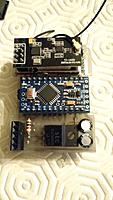
|
||||

|
||||
|
||||
or build your own board using SMD components and an associated PCB:
|
||||
or build your own board using [SMD components](http://www.rcgroups.com/forums/showpost.php?p=31064232&postcount=1020) and an [associated PCB](https://oshpark.com/shared_projects/MaGYDg0y):
|
||||
|
||||
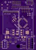
|
||||
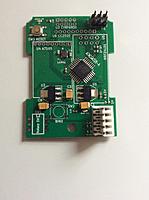
|
||||
 
|
||||
|
||||
If you build this PCB v2.3c and want to enable serial mode for er9x/ersky9x, you should do [this mod](http://static.rcgroups.net/forums/attachments/4/0/8/5/8/3/a8180322-194-multi.jpg):
|
||||

|
||||
|
||||
|
||||
###Schematic
|
||||
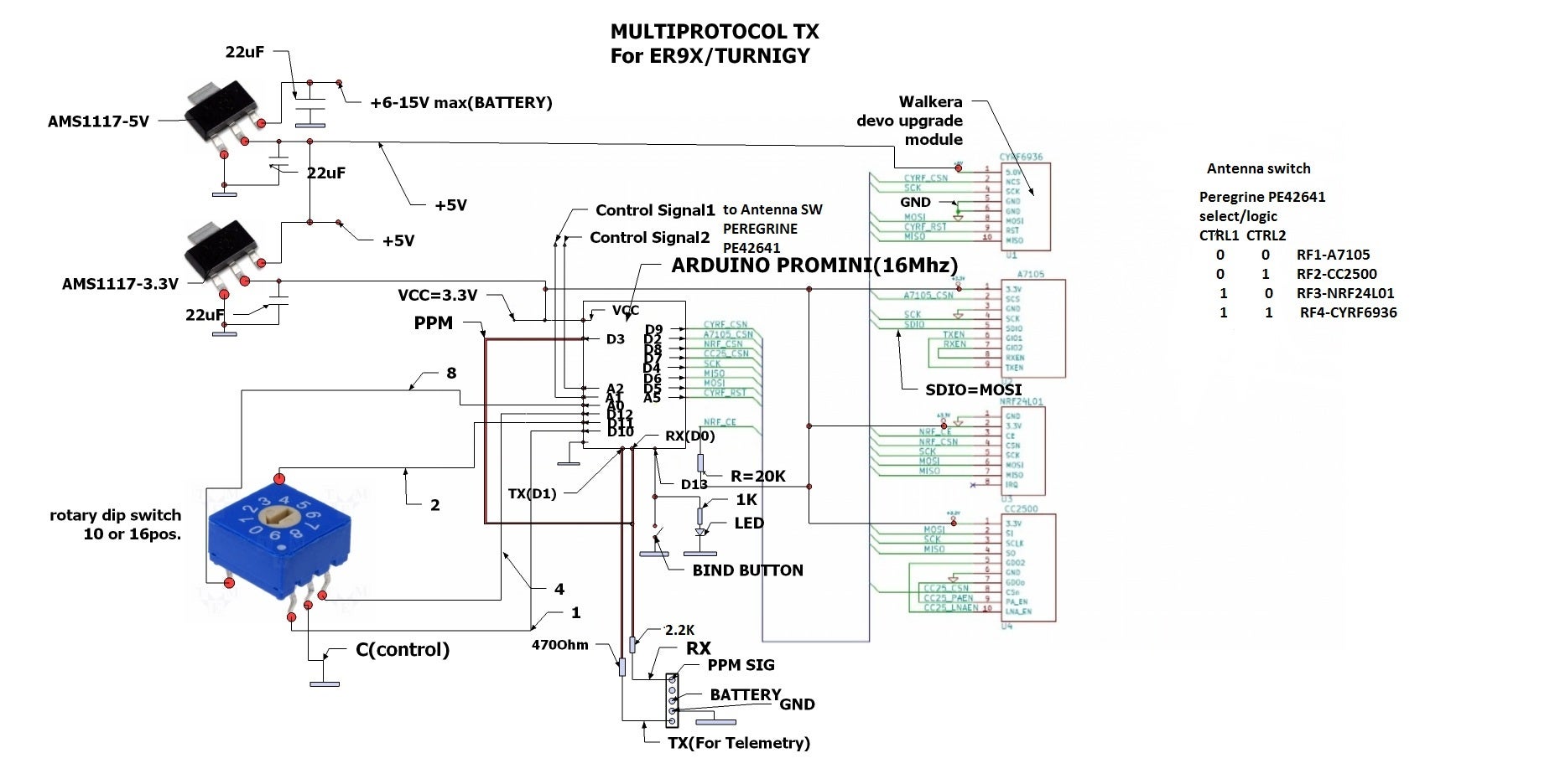
|
||||
|
||||
@@ -334,15 +477,17 @@ You can 3D print your box (details [here](http://www.rcgroups.com/forums/showpos
|
||||
##Compilation and programmation
|
||||
|
||||
###Toolchain
|
||||
Arduino 1.6.5
|
||||
Supported Arduino version is [1.6.7](https://www.arduino.cc/download_handler.php?f=/arduino-1.6.7-windows.exe). Make sure to select "Arduino Pro or Pro Mini, ATmega328 (5V,16MHz)" before compiling.
|
||||
|
||||
Compilation of the code posted here works. So if it doesn't for you this is a problem with your setup, please double check everything before asking.
|
||||
|
||||
Multiprotocol.ino header can be modified to compile with/without some protocols, change protocols/sub_protocols associated with dial for PPM input, different channel orders, different channels timing, 8 or 16 channels serial protocol, Telemetry or not, ...
|
||||
_Config.h file can be modified to compile with/without some protocols, change protocols/sub_protocols/settings associated with dial for PPM input, different channel orders, different channels timing, Telemetry or not, ...
|
||||
|
||||
###Upload the code using ISP (In System Programming)
|
||||
It is recommended to use an external programmer like [USBASP](http://www.banggood.com/USBASP-USBISP-3_3-5V-AVR-Downloader-Programmer-With-ATMEGA8-ATMEGA128-p-934425.html) to upload the code in the Atmega328. The programmer should be set to 3.3V or nothing to not supply any over voltage to the multimodule and avoid any damages.
|
||||
|
||||
The dial must be set to 0 before flashing!
|
||||
|
||||
From the Arduino environment, you can use this shortcut to compile and upload to the module: Skecth->Upload Using Programmer (Ctrl+Maj+U)
|
||||
|
||||
To flash the latest provided hex file under [Release](https://github.com/pascallanger/DIY-Multiprotocol-TX-Module/releases), you can use a tool like [AVR Burn-O-Mat](http://avr8-burn-o-mat.aaabbb.de/), set the microcontroller to m328p and flash it.
|
||||
@@ -359,14 +504,17 @@ This will make sure your ATMEGA328 is well configured and the global TX ID is no
|
||||
|
||||
###LED status
|
||||
- off: program not running or a protocol selected with the associated module not installed.
|
||||
- flash: invalid protocol selected (excluded from compilation or invalid protocol number)
|
||||
- slow blink: serial has been selected but no valid signal has been seen on the RX pin.
|
||||
- fast blink: bind in progress.
|
||||
- on: normal operation.
|
||||
|
||||
###Bind
|
||||
Make sure to follow this procedure: press the bind button, apply power and then release it after 1sec. The LED should be blinking fast indicating a bind status and then fixed on. It's normal that the LED turns off when you press the bind button, this behavior is not controlled by the Atmega328.
|
||||
Make sure to follow this procedure: press the bind button, apply power and then release it after 1sec. The LED should be blinking fast indicating a bind status and then fixed on when the bind period is over. It's normal that the LED turns off when you press the bind button, this behavior is not controlled by the Atmega328.
|
||||
For serial, the preffered method is to bind via the GUI protocol page.
|
||||
|
||||
It migth happen that your module is always binding at power up. If this is the case, there is a big chance that you are using an Arduino Pro Mini with an external status LED. To work around this issue connect a 10K resistor between D13 and 3.3V.
|
||||
|
||||
###Protocol selection
|
||||
For serial, leave all 4 selection pins unconnected.
|
||||
For PPM, connect 1 to 4 of the selection protocol pins to GND.
|
||||
|
||||
Reference in New Issue
Block a user