**To download the latest compiled version (hex file), click on [Release](https://github.com/pascallanger/DIY-Multiprotocol-TX-Module/releases) on the top menu.**
The multiprotocol TX module takes full advantage of being used on a Turnigy 9X, 9XR, 9XR Pro, Taranis, 9Xtreme, AR9X, ... running [er9x](http://openrcforums.com/forum/viewtopic.php?f=5&t=4598) or [ersky9X](http://openrcforums.com/forum/viewtopic.php?f=7&t=4676). An OpenTX version for Taranis is available [here](http://plaisthos.de/opentx/).
This enables full integration using the radio GUI to setup models with all the available protocols options.
- Protocol and type: many main protocols have variants
- RX Num: number your different RXs and make sure only one model will react to the commands
- Power: High or low, enables to lower the power setting of your TX (indoor for example).
- Option: -127..+127 allowing to set specific protocol options. Like for Hubsan to set the video frequency.
- Bind: bind a RX/model
- Autobind: Yes or No. At the model selection (or power applied to the TX) a bind sequence will be initiated
- Range: test range by setting the transmission power to the lowest value
Notes:
- Using this solution does not need any modification of the TX since it uses the TX module slot PPM pin for serial transfer.
- There are 2 versions of serial protocol either 8 or 16 channels. 16 channels is the latest and only available version going forward. Make sure to use the right version based on your version of er9x/ersky9x.
- Channels order is AETR by default but can be changed in _Config.h.
There are 4 protocols supporting telemetry: Hubsan, DSM, FrSkyD and FrSkyX.
Hubsan displays the battery voltage and TX RSSI.
DSM displays TX RSSI and full telemetry.
FrSkyD displays full telemetry (A0, A1, RX RSSI, TX RSSI and Hub).
FrSkyX displays full telemetry (A1, A2, RX RSSI, TX RSSI and Hub).
### If used in PPM mode
Telemetry is available as a serial 9600 8 n 1 output on the TX pin of the Atmega328p using the FrSky hub format for Hubsan, FrSkyD, FrSkyX and DSM format for DSM2/X.
You can connect it to your TX if it is telemetry enabled or use a bluetooth adapter (HC05/HC06) along with an app on your phone/tablet ([app example](https://play.google.com/store/apps/details?id=biz.onomato.frskydash&hl=fr)) to display telemetry information and setup alerts.
### If used in Serial mode
Telemetry is built in for er9x and ersky9x TXs.
To enable telemetry on a Turnigy 9X or 9XR you need to modify your TX following one of the Frsky mod like this [one](http://blog.oscarliang.net/turnigy-9x-advance-mod/).
Note: DSM telemetry is not available on er9x due to a lack of flash space.
Enabling telemetry on a 9XR PRO and may be other TXs does not require any hardware modifications. The additional required serial pin is already available on the TX back module pins.
Once the TX is telemetry enabled, it just needs to be configured on the model (see er9x/ersky9x documentation).
- [A7105](http://www.banggood.com/XL7105-D03-A7105-Modification-Module-Support-Deviation-Galee-Flysky-p-922603.html) for Flysky, Hubsan
- [CC2500](http://www.banggood.com/CC2500-PA-LNA-Romote-Wireless-Module-CC2500-SI4432-NRF24L01-p-922595.html) for FrSkyV, FrSkyD, FrSkyX and SFHSS
- [CYRF6936](http://www.ehirobo.com/walkera-wk-devo-s-mod-devo-8-or-12-to-devo-8s-or-12s-upgrade-module.html) for DSM, DEVO, J6Pro
- [NRF24L01](http://www.banggood.com/2_4G-NRF24L01-PA-LNA-Wireless-Module-1632mm-Without-Antenna-p-922601.html) for Hisky, V2x2, CX-10, SYMAX and plenty other protocols
RF modules can be installed for protocols need only. Example: if you only need the Hubsan protocol then install only a A7105 on your board.
You also need some [antennas](http://www.banggood.com/2_4GHz-3dBi-RP-SMA-Connector-Booster-Wireless-Antenna-Modem-Router-p-979407.html) and [cables](http://www.banggood.com/10cm-PCI-UFL-IPX-to-RPSMA-Female-Jack-Pigtail-Cable-p-924933.html).
The main program is running on an ATMEGA328p running @16MHz and 3.3V.
An [Arduino pro mini 16Mhz/5V](http://www.banggood.com/Wholesale-New-Ver-Pro-Mini-ATMEGA328-328p-5V-16MHz-Arduino-Compatible-Nano-Size-p-68534.html) powered at 3.3V (yes it works) can be used to build your own Multimodule. An Arduino Mini based on Atmega328p can also be used.
#### Build your own board using [SMD components](http://www.rcgroups.com/forums/showpost.php?p=31064232&postcount=1020) and an [associated PCB v2.3c](https://oshpark.com/shared_projects/MaGYDg0y):
If you build this PCB v2.3c and want to enable serial mode for er9x/ersky9x, you have to do [this mod](http://static.rcgroups.net/forums/attachments/4/0/8/5/8/3/a8667856-242-multi.jpg).
Repository includes Kicad files of schematic and pcb. This is a variant of the Multipro V2.3c circuit design. It is basicly the same as the 2.3c board as far as component placement goes. What's changed is the added resistors for the serial protocol and also
the addition of solder jumpers on the bottom of the board for the various options to connect the TX, RX, and PPM
This module can be purchased [here](http://www.banggood.com/2_4G-CC2500-A7105-Flysky-Frsky-Devo-DSM2-Multiprotocol-TX-Module-With-Antenna-p-1048377.html). All the 4 RF modules are already implemented A7105, NRF24L01, CC2500 and CYRF6936. The board is also equiped with an antenna switcher which means only one antenna for all.
**It is highly recommended to update the firmware** of this board as it is distributed with a really old and bugged one. For this you have to solder a 6 pin header (top left) and use an USBASP like explained [below](https://github.com/pascallanger/DIY-Multiprotocol-TX-Module#upload-the-code-using-isp-in-system-programming).
If you want to enable serial mode for er9x/ersky9x/Taranis/... and depending on your board revision, you have to do one of these modifications:
- 1st revision, add 2 resistors as shown here: 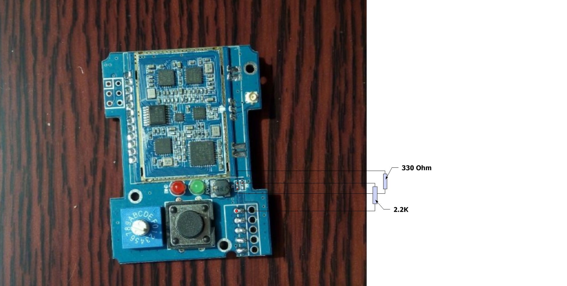
Note: if you have the 1st board revision (check pictures above), sometime bind occures at power up even without pressing the bind button or not having an autobind protocol. To solve this issue, replacing the BIND led resistor (on the board back) of 1.2K by a 4.7K.
If you build your own version of the board you can 3D print this case (details [here](http://www.rcgroups.com/forums/showpost.php?p=33294140&postcount=2034)):
If you have the Banggood ready to use board you can 3D print this case (details [here](http://www.rcgroups.com/forums/showpost.php?p=35349049&postcount=3)):
Multiprotocol source can be compiled using the Arduino IDE.
The currently supported Arduino version is [1.6.10](https://www.arduino.cc/download_handler.php?f=/arduino-1.6.10-windows.exe).
Download the [zip file](https://github.com/pascallanger/DIY-Multiprotocol-TX-Module/archive/master.zip) of this repository, unzip it in a folder, navigate to the Multiprotocol directory and then click on Multiprotocol.ino. The Arduino environment will appear and the Multiprotocol project will be loaded.
**[_Config.h file](https://github.com/pascallanger/DIY-Multiprotocol-TX-Module/blob/master/Multiprotocol/_Config.h) must be modified** to select which protocols will be available, change protocols/sub_protocols/settings associated with dial for PPM input, different TX channel orders and timing, Telemetry or not, ...
This is mandatory since all available protocols will not fit in the ATmega328. You need to pick and choose what you want.
Notes:
- Make sure to select "Arduino Pro or Pro Mini, ATmega328 (5V,16MHz)" before compiling.
- Compilation of the code posted here works. So if it doesn't for you this is a problem with your setup, please double check everything before asking.
- If you want to reduce the code size even further, you can modify the file platform.txt located in "C:\Program Files (x86)\Arduino\hardware\arduino\avr". Set the line "compiler.c.elf.extra_flags=" to "compiler.c.elf.extra_flags=-Wl,--relax".
It is recommended to use an external programmer like [USBASP](http://www.banggood.com/USBASP-USBISP-3_3-5V-AVR-Downloader-Programmer-With-ATMEGA8-ATMEGA128-p-934425.html) to upload the code in the Atmega328. The programmer should be set to 3.3V or nothing to not supply any over voltage to the multimodule and avoid any damages.
The dial must be set to 0 before flashing!
From the Arduino environment, you can use this shortcut to compile and upload to the module: Skecth->Upload Using Programmer (Ctrl+Maj+U)
To flash the latest provided hex file under [Release](https://github.com/pascallanger/DIY-Multiprotocol-TX-Module/releases), you can use a tool like [AVR Burn-O-Mat](http://avr8-burn-o-mat.aaabbb.de/), set the microcontroller to m328p and flash it.
Use this method only for Arduino Pro Mini boards with bootloader.
Use an external FTDI adapter like [this one](http://www.banggood.com/FT232RL-FTDI-USB-To-TTL-Serial-Converter-Adapter-Module-For-Arduino-p-917226.html).
The programmer should be set to 3.3V or nothing to not supply any over voltage to the multimodule and avoid any damages.
From the Arduino environment, you can use Upload button which will compile and upload to the module: Skecth->Upload (Ctrl+U)
To upload the latest provided hex file under [Release](https://github.com/pascallanger/DIY-Multiprotocol-TX-Module/releases), you can use a tool like [XLoader](http://russemotto.com/xloader/), set the microcontroller to Atmega328 and upload it.
- Make sure you have done the mods to the v2.3c PCB by adding the 2.2k and 470 ohm resistors as indicated in the [Board section] (https://github.com/pascallanger/DIY-Multiprotocol-TX-Module#board).
Make sure to follow this procedure: press the bind button, apply power and then release it after 1sec. The LED should be blinking fast indicating a bind status and then fixed on when the bind period is over. It's normal that the LED turns off when you press the bind button, this behavior is not controlled by the Atmega328.
For serial, the preffered method is to bind via the GUI protocol page.
If your module is always/sometime binding at power up without pressing the button:
- Arduino Pro Mini with an external status LED: to work around this issue connect a 10K resistor between D13 and 3.3V.
- 4in1 module V1 (check 4in1 pictures): to solve this issue, replacing the BIND led resistor (on the board back) of 1.2K by a 4.7K.
You can report your problem using the [GitHub issue](https://github.com/pascallanger/DIY-Multiprotocol-TX-Module/issues) system or go to the [Main thread on RCGROUPS](http://www.rcgroups.com/forums/showthread.php?t=2165676) to ask your question.
Please provide the following information:
- Multiprotocol code version
- TX type
- Using PPM or Serial, if using er9x or ersky9x the version in use
- Different led status (multimodule and model)
- Explanation of the behavior and reproduction steps